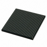
MCIMX515CJM6C Freescale Semiconductor, MCIMX515CJM6C Datasheet - Page 124

MCIMX515CJM6C
Manufacturer Part Number
MCIMX515CJM6C
Description
MULTIMEDIA PROC 529-LFBGA
Manufacturer
Freescale Semiconductor
Series
i.MX51r
Datasheets
1.MCIMX512DJM8C.pdf
(200 pages)
2.MCIMX515DJM8C.pdf
(2 pages)
3.MCIMX512CJM6C.pdf
(198 pages)
Specifications of MCIMX515CJM6C
Core Processor
ARM Cortex-A8
Core Size
32-Bit
Speed
600MHz
Connectivity
1-Wire, EBI/EMI, Ethernet, I²C, IrDA, MMC, SPI, SSI, UART/USART, USB OTG
Peripherals
DMA, I²S, LCD, POR, PWM, WDT
Number Of I /o
128
Program Memory Type
ROMless
Ram Size
128K x 8
Voltage - Supply (vcc/vdd)
0.8 V ~ 1.15 V
Oscillator Type
External
Operating Temperature
-20°C ~ 85°C
Package / Case
529-LFBGA
Processor Series
i.MX51
Core
ARM Cortex A8
Data Bus Width
32 bit
Program Memory Size
36 KB
Data Ram Size
128 KB
Interface Type
I2C, SPI, SSI, UART, USB
Maximum Clock Frequency
200 MHz
Number Of Timers
5
Operating Supply Voltage
0.8 V to 1.15 V
Maximum Operating Temperature
+ 95 C
Mounting Style
SMD/SMT
3rd Party Development Tools
MDK-ARM, RL-ARM, ULINK2
Development Tools By Supplier
MCIMX51EVKJ
Minimum Operating Temperature
- 40 C
Lead Free Status / RoHS Status
Lead free / RoHS Compliant
Eeprom Size
-
Program Memory Size
-
Data Converters
-
Lead Free Status / Rohs Status
Lead free / RoHS Compliant
Available stocks
Company
Part Number
Manufacturer
Quantity
Price
Company:
Part Number:
MCIMX515CJM6C
Manufacturer:
Freescale Semiconductor
Quantity:
10 000
Part Number:
MCIMX515CJM6C
Manufacturer:
FREESCALE
Quantity:
20 000
Company:
Part Number:
MCIMX515CJM6CR2
Manufacturer:
Freescale Semiconductor
Quantity:
10 000
1
2
3
4
5
Electrical Characteristics
4.7.12
This section describes the electrical parameters of the SIM module. Each SIM module interface consists
of 12 signals (two separate ports each containing six signals). Typically a a port uses five signals.
The interface is designed to be used with synchronous SIM cards meaning the SIM module provides the
clock used by the SIM card. The clock frequency is typically 372 times the Tx/Rxdata rate, however the
SIM module can work with CLK frequencies of 16 times the Tx/Rx data rate.
There is no timing relationship between the clock and the data. The clock that the SIM module provides
to the SIM card is used by the SIM card to recover the clock from the data in the same manner as standard
UART data exchanges. All six signals (5 for bi-directional Tx/Rx) of the SIM module are asynchronous
to each other.
There are no required timing relationships between signals in normal mode. The SIM card is initiated by
the interface device; the SIM card responds with Answer to Reset. Although the SIM interface has no
defined requirements, the ISO-7816 defines reset and power-down sequences. (For detailed information,
see ISO-7816.)
Table 97
124
50% duty cycle clock
With C = 50 pF
With C = 50 pF
With Cin = 30 pF, Cout = 30 pF
With Cin = 30 pF
SI1
SI2
SI3
SI4
SI5
SI6
ID
SIMx_CLKy
SIM RST Rise Time / Fall Time(SIMx_RSTy)
defines the general timing requirements for the SIM interface.
(SIMx_DATAy_RX_TX, SIMx_SIMPDy)
SIM (Subscriber Identification Module) Timing
SIM Clock Frequency (SIMx_CLKy)
SIM Clock Rise Time (SIMx_CLKy)
SIM Clock Fall Time (SIMx_CLKy)
Time(SIMx_DATAy_RX_TX)
SIM Input Transition Time
SIM I/O Rise Time / Fall
i.MX51 Applications Processors for Consumer and Industrial Products, Rev. 4
Parameter
Table 97. SIM Timing Parameters, High Drive Strength
Figure 83. SIM Clock Timing Diagram
SI3
4
3
2
1
,
5
Symbol
S
S
Tr/Tf
Tr/Tf
S
S
trans
freq
rise
fall
1/SI1
SI2
0.01
Min
—
—
10
—
—
0.09
0.09
×
×
Max
25
25
(1/S
(1/S
Freescale Semiconductor
1
1
freq
freq
)
)
MHz
Unit
µ
µ
ns
ns
ns
s
s


