ATTINY44-15MZ Atmel, ATTINY44-15MZ Datasheet - Page 152
ATTINY44-15MZ
Manufacturer Part Number
ATTINY44-15MZ
Description
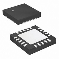
MCU AVR 4K FLASH 15MHZ 20-QFN
Manufacturer
Atmel
Series
AVR® ATtinyr
Datasheet
1.ATTINY44-15MZ.pdf
(225 pages)
Specifications of ATTINY44-15MZ
Package / Case
20-QFN Exposed Pad
Voltage - Supply (vcc/vdd)
2.7 V ~ 5.5 V
Operating Temperature
-40°C ~ 125°C
Speed
16MHz
Number Of I /o
12
Eeprom Size
256 x 8
Core Processor
AVR
Program Memory Type
FLASH
Ram Size
256 x 8
Program Memory Size
4KB (4K x 8)
Data Converters
A/D 8x10b
Oscillator Type
Internal
Peripherals
Brown-out Detect/Reset, POR, PWM, WDT
Connectivity
USI
Core Size
8-Bit
Processor Series
ATTINY4x
Core
AVR8
Data Bus Width
8 bit
Data Ram Size
256 B
Interface Type
SPI, UART
Maximum Clock Frequency
16 MHz
Number Of Programmable I/os
12
Number Of Timers
2
Maximum Operating Temperature
+ 85 C
Mounting Style
SMD/SMT
3rd Party Development Tools
EWAVR, EWAVR-BL
Development Tools By Supplier
ATAVRDRAGON, ATSTK500, ATSTK600, ATAVRISP2, ATAVRONEKIT
Minimum Operating Temperature
- 40 C
On-chip Adc
10 bit, 8 Channel
Lead Free Status / RoHS Status
Lead free / RoHS Compliant
Available stocks
Company
Part Number
Manufacturer
Quantity
Price
Company:

Part Number:
ATTINY44-15MZ
Manufacturer:
ATMEL
Quantity:
1 000
Part Number:
ATTINY44-15MZ
Manufacturer:
ATMEL/爱特梅尔
Quantity:
20 000


18.10.2
152
Atmel ATtiny24/44/84 [Preliminary]
ADCSRA – ADC Control and Status Register A
• Bit 7 – ADEN: ADC Enable
Writing this bit to logical one enables the ADC. By writing it to zero, the ADC is turned off.
Turning the ADC off while a conversion is in progress will terminate the conversion.
• Bit 6 – ADSC: ADC Start Conversion
In single-conversion mode, write this bit to logical one to start each conversion. In free running
mode, write this bit to logical one to start the first conversion. The first conversion after ADSC
has been written and after the ADC has been enabled, or if ADSC is written at the same time
as the ADC is enabled, will take 25 ADC clock cycles instead of the normal 13. This first con-
version initializes the ADC.
ADSC will read as one as long as a conversion is in progress. When the conversion is com-
plete, it returns to zero. Writing logical zero to this bit has no effect.
• Bit 5 – ADATE: ADC Auto Trigger Enable
When this bit is written to logical one, auto triggering of the ADC is enabled. The ADC will start
a conversion on a positive edge of the selected trigger signal. The trigger source is selected by
setting the ADC trigger select bits (ADTS in ADCSRB).
• Bit 4 – ADIF: ADC Interrupt Flag
This bit is set when an ADC conversion completes and the data registers are updated. The
ADC conversion complete interrupt is executed if the ADIE bit and the I-bit in SREG are set.
ADIF is cleared by hardware when executing the corresponding interrupt handling vector.
Alternatively, ADIF is cleared by writing a logical one to the flag. Beware that if performing a
read-modify-write on ADCSRA, a pending interrupt can be disabled. This also applies if the
SBI instruction is used.
• Bit 3 – ADIE: ADC Interrupt Enable
When this bit is written to logical one and the I-bit in SREG is set, the ADC conversion com-
plete interrupt is activated.
• Bits 2:0 – ADPS2:0: ADC Prescaler Select Bits
These bits determine the division factor between the system clock frequency and the input
clock to the ADC.
Table 18-6.
Bit
0x06 (0x26)
Read/Write
Initial Value
ADPS2
0
0
0
0
ADC Prescaler Selections
ADEN
R/W
7
0
ADSC
R/W
ADPS1
6
0
0
0
1
1
ADATE
R/W
5
0
ADIF
R/W
4
0
ADPS0
0
1
0
1
ADIE
R/W
3
0
ADPS2
R/W
2
0
ADPS1
Division Factor
R/W
1
0
2
2
4
8
ADPS0
R/W
0
0
7701E–AVR–02/11
ADCSRA
Related parts for ATTINY44-15MZ
Image
Part Number
Description
Manufacturer
Datasheet
Request
R

Part Number:
Description:
Manufacturer:
Atmel Corporation
Datasheet:
Part Number:
Description:
Manufacturer:
Atmel Corporation
Datasheet:

Part Number:
Description:
IC MCU AVR 4K FLASH 20MHZ 20-QFN
Manufacturer:
Atmel
Datasheet:

Part Number:
Description:
IC MCU AVR 4K FLASH 20MHZ 14SOIC
Manufacturer:
Atmel
Datasheet:

Part Number:
Description:
MCU AVR 4KB FLASH 20MHZ 14SOIC
Manufacturer:
Atmel
Datasheet:
Part Number:
Description:
MCU AVR 4KB FLASH 20MHZ 20QFN
Manufacturer:
Atmel
Datasheet:
Part Number:
Description:
IC MCU AVR 4K FLASH 15MHZ 14SOIC
Manufacturer:
Atmel
Datasheet:

Part Number:
Description:
IC MCU AVR 4K FLASH 20MHZ 14-DIP
Manufacturer:
Atmel
Datasheet:
Part Number:
Description:
Manufacturer:
Atmel Corporation
Datasheet:
Part Number:
Description:
Microcontrollers (MCU) 512B FL 32B SRAM TIMER ATTINY4 12MHz
Manufacturer:
Atmel
Part Number:
Description:
IC MCU AVR 512B FLASH SOT-23-6
Manufacturer:
Atmel
Datasheet:

Part Number:
Description:
IC MCU AVR 512B FLASH SOT-23-6
Manufacturer:
Atmel
Datasheet: