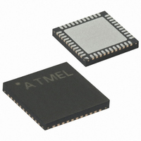
ATXMEGA16A4-MH Atmel, ATXMEGA16A4-MH Datasheet - Page 96

ATXMEGA16A4-MH
Manufacturer Part Number
ATXMEGA16A4-MH
Description
MCU AVR 16K FLASH 1.6V 44-QFN
Manufacturer
Atmel
Series
AVR® XMEGAr
Datasheet
1.ATXMEGA16A4-CUR.pdf
(108 pages)
Specifications of ATXMEGA16A4-MH
Core Processor
AVR
Core Size
8/16-Bit
Speed
32MHz
Connectivity
I²C, IrDA, SPI, UART/USART
Peripherals
Brown-out Detect/Reset, DMA, POR, PWM, WDT
Number Of I /o
34
Program Memory Size
16KB (8K x 16)
Program Memory Type
FLASH
Eeprom Size
1K x 8
Ram Size
2K x 8
Voltage - Supply (vcc/vdd)
1.6 V ~ 3.6 V
Data Converters
A/D 12x12b, D/A 2x12b
Oscillator Type
Internal
Operating Temperature
-40°C ~ 85°C
Package / Case
44-VQFN Exposed Pad
Processor Series
ATXMEGA16x
Core
AVR8
Data Bus Width
8 bit, 16 bit
Data Ram Size
2 KB
Interface Type
I2C, SPI, USART
Maximum Clock Frequency
32 MHz
Number Of Programmable I/os
36
Number Of Timers
5
Operating Supply Voltage
1.6 V to 3.6 V
Maximum Operating Temperature
+ 85 C
Mounting Style
SMD/SMT
3rd Party Development Tools
EWAVR, EWAVR-BL
Development Tools By Supplier
ATAVRDRAGON, ATAVRISP2, ATAVRONEKIT
Minimum Operating Temperature
- 40 C
On-chip Adc
12 bit, 1 Channel
On-chip Dac
2 bit, 1 Channel
Package
44VFBGA EP
Device Core
AVR
Family Name
XMEGA
Maximum Speed
32 MHz
For Use With
ATAVRONEKIT - KIT AVR/AVR32 DEBUGGER/PROGRMMRATSTK600-TQFP44 - STK600 SOCKET/ADAPTER 44-TQFP770-1007 - ISP 4PORT ATMEL AVR MCU SPI/JTAG770-1004 - ISP 4PORT FOR ATMEL AVR MCU SPIATAVRISP2 - PROGRAMMER AVR IN SYSTEM
Lead Free Status / RoHS Status
Lead free / RoHS Compliant
Other names
ATXMEGA16A4-MU
ATXMEGA16A4-MU
ATXMEGA16A4-MU
8069Q–AVR–12/10
11. Sampled BOD in Active mode will cause noise when bandgap is used as reference
12. DAC is nonlinear and inaccurate when reference is above 2.4V or VCC - 0.6V
13.
14. EEPROM page buffer always written when NVM DATA0 is written
15. Pending full asynchronous pin change interrupts will not wake the device
16. Pin configuration does not affect Analog Comparator output
Problem fix/Workaround
Do not set the BOD level higher than VCC even if the BOD is not used.
Using the BOD in sampled mode when the device is running in Active or Idle mode will add
noise on the bandgap reference for ADC, DAC and Analog Comparator.
Problem fix/Workaround
If the bandgap is used as reference for either the ADC, DAC or the Analog Comparator, the
BOD must not be set in sampled mode.
Using the DAC with a reference voltage above 2.4V or VCC - 0.6V will give inaccurate out-
put when converting codes that give below 0.75V output:
– ±10 LSB for continuous mode
– ±200 LSB for Sample and Hold mode
Problem fix/Workaround
None.
DAC has increased INL or noise for some operating conditions
Some DAC configurations or operating condition will result in increased output error.
– Continous mode: ±5 LSB
– Sample and hold mode: ±15 LSB
– Sample and hold mode for reference above 2.0v: up to ±100 LSB
Problem fix/Workaround
None.
If the EEPROM is memory mapped, writing to NVM DATA0 will corrupt data in the EEPROM
page buffer.
Problem fix/Workaround
Before writing to NVM DATA0, for example when doing software CRC or flash page buffer
write, check if EEPROM page buffer active loading flag (EELOAD) is set. Do not write NVM
DATA0 when EELOAD is set.
Any full asynchronous pin-change Interrupt from pin 2, on any port, that is pending when the
sleep instruction is executed, will be ignored until the device is woken from another source
or the source triggers again. This applies when entering all sleep modes where the System
Clock is stopped.
Problem fix/Workaround
None.
The Output/Pull and inverted pin configuration does not affect the Analog Comparator
output.
Problem fix/Workaround
None for Output/Pull configuration.
XMEGA A4
96


