MC9S08JM8CGT Freescale Semiconductor, MC9S08JM8CGT Datasheet - Page 188
MC9S08JM8CGT
Manufacturer Part Number
MC9S08JM8CGT
Description
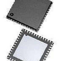
MCU 8BIT 8K FLASH 48-QFN
Manufacturer
Freescale Semiconductor
Series
HCS08r
Datasheet
1.DEMO9S08JM16.pdf
(386 pages)
Specifications of MC9S08JM8CGT
Core Processor
HCS08
Core Size
8-Bit
Speed
48MHz
Connectivity
I²C, LIN, SCI, SPI, USB
Peripherals
LVD, POR, PWM, WDT
Number Of I /o
37
Program Memory Size
8KB (8K x 8)
Program Memory Type
FLASH
Ram Size
1K x 8
Voltage - Supply (vcc/vdd)
2.7 V ~ 5.5 V
Data Converters
A/D 8x12b
Oscillator Type
External
Operating Temperature
-40°C ~ 85°C
Package / Case
48-QFN Exposed Pad
Processor Series
S08JM
Core
HCS08
Data Bus Width
8 bit
Data Ram Size
1 KB
Interface Type
I2C, SPI
Maximum Clock Frequency
48 MHz
Number Of Programmable I/os
37
Number Of Timers
2
Operating Supply Voltage
2.7 V to 5.5 V
Maximum Operating Temperature
+ 85 C
Mounting Style
SMD/SMT
3rd Party Development Tools
EWS08
Development Tools By Supplier
DEMOJM, DEMOJMSKT, DEMOFLEXISJMSD, DEMO9S08JM16
Minimum Operating Temperature
- 40 C
On-chip Adc
12 bit, 8 Channel
Package
48QFN EP
Family Name
HCS08
Maximum Speed
48 MHz
Lead Free Status / RoHS Status
Lead free / RoHS Compliant
Eeprom Size
-
Lead Free Status / Rohs Status
Lead free / RoHS Compliant


Multi-Purpose Clock Generator (S08MCGV1)
12.4
12.4.1
The nine states of the MCG are shown as a state diagram and are described below. The arrows indicate the
allowed movements between the states.
12.4.1.1
FLL engaged internal (FEI) is the default mode of operation and is entered when all the following
conditions occur:
188
IREFS=1
CLKS=01
BDM Disabled
and LP=1
•
•
•
•
CLKS bits are written to 00
IREFS bit is written to 1
PLLS bit is written to 0
RDIV bits are written to 000. Because the internal reference clock frequency must already be in
the range of 31.25 kHz to 39.0625 kHz after it is trimmed, no further frequency divide is necessary.
Functional Description
Operational Modes
FLL Engaged Internal (FEI)
Internal (BLPI)
Low Power
Entered from any state
when MCU enters stop
Bypassed
BDM Enabled
or LP=0
IREFS=1
CLKS=00
PLLS=0
IREFS=1
CLKS=01
PLLS=0
Figure 12-8. Clock Switching Modes
FLL Engaged
Internal (FEI)
MC9S08JM16 Series Data Sheet, Rev. 2
FLL Bypassed
Internal (FBI)
Stop
FLL Engaged
External (FEE)
PLL Bypassed
External (PBE)
FLL Bypassed
External (FBE)
PLL Engaged
External (PEE)
Returns to state that was active
before MCU entered stop, unless
RESET occurs while in stop.
IREFS=0
CLKS=00
PLLS=0
BDM Enabled
or LP=0
BDM Enabled
or LP=0
IREFS=0
CLKS=10
PLLS=0
IREFS=0
CLKS=10
PLLS=1
IREFS=0
CLKS=00
PLLS=1
External (BLPE)
Low Power
Bypassed
Freescale Semiconductor
IREFS=0
CLKS=10
BDM Disabled
and LP=1
Related parts for MC9S08JM8CGT
Image
Part Number
Description
Manufacturer
Datasheet
Request
R

Part Number:
Description:
Manufacturer:
Freescale Semiconductor, Inc
Datasheet:
Part Number:
Description:
Manufacturer:
Freescale Semiconductor, Inc
Datasheet:
Part Number:
Description:
Manufacturer:
Freescale Semiconductor, Inc
Datasheet:
Part Number:
Description:
Manufacturer:
Freescale Semiconductor, Inc
Datasheet:
Part Number:
Description:
Manufacturer:
Freescale Semiconductor, Inc
Datasheet:
Part Number:
Description:
Manufacturer:
Freescale Semiconductor, Inc
Datasheet:
Part Number:
Description:
Manufacturer:
Freescale Semiconductor, Inc
Datasheet:
Part Number:
Description:
Manufacturer:
Freescale Semiconductor, Inc
Datasheet:
Part Number:
Description:
Manufacturer:
Freescale Semiconductor, Inc
Datasheet:
Part Number:
Description:
Manufacturer:
Freescale Semiconductor, Inc
Datasheet:
Part Number:
Description:
Manufacturer:
Freescale Semiconductor, Inc
Datasheet:
Part Number:
Description:
Manufacturer:
Freescale Semiconductor, Inc
Datasheet:
Part Number:
Description:
Manufacturer:
Freescale Semiconductor, Inc
Datasheet:
Part Number:
Description:
Manufacturer:
Freescale Semiconductor, Inc
Datasheet:
Part Number:
Description:
Manufacturer:
Freescale Semiconductor, Inc
Datasheet: