MC9S08JM8CGT Freescale Semiconductor, MC9S08JM8CGT Datasheet - Page 49
MC9S08JM8CGT
Manufacturer Part Number
MC9S08JM8CGT
Description
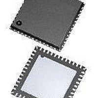
MCU 8BIT 8K FLASH 48-QFN
Manufacturer
Freescale Semiconductor
Series
HCS08r
Datasheet
1.DEMO9S08JM16.pdf
(386 pages)
Specifications of MC9S08JM8CGT
Core Processor
HCS08
Core Size
8-Bit
Speed
48MHz
Connectivity
I²C, LIN, SCI, SPI, USB
Peripherals
LVD, POR, PWM, WDT
Number Of I /o
37
Program Memory Size
8KB (8K x 8)
Program Memory Type
FLASH
Ram Size
1K x 8
Voltage - Supply (vcc/vdd)
2.7 V ~ 5.5 V
Data Converters
A/D 8x12b
Oscillator Type
External
Operating Temperature
-40°C ~ 85°C
Package / Case
48-QFN Exposed Pad
Processor Series
S08JM
Core
HCS08
Data Bus Width
8 bit
Data Ram Size
1 KB
Interface Type
I2C, SPI
Maximum Clock Frequency
48 MHz
Number Of Programmable I/os
37
Number Of Timers
2
Operating Supply Voltage
2.7 V to 5.5 V
Maximum Operating Temperature
+ 85 C
Mounting Style
SMD/SMT
3rd Party Development Tools
EWS08
Development Tools By Supplier
DEMOJM, DEMOJMSKT, DEMOFLEXISJMSD, DEMO9S08JM16
Minimum Operating Temperature
- 40 C
On-chip Adc
12 bit, 8 Channel
Package
48QFN EP
Family Name
HCS08
Maximum Speed
48 MHz
Lead Free Status / RoHS Status
Lead free / RoHS Compliant
Eeprom Size
-
Lead Free Status / Rohs Status
Lead free / RoHS Compliant


Aborting a command in this way sets the FACCERR access error flag which must be cleared before
starting a new command.
A strictly monitored procedure must be obeyed or the command will not be accepted. This minimizes the
possibility of any unintended changes to the flash memory contents. The command complete flag (FCCF)
indicates when a command is complete. The command sequence must be completed by clearing FCBEF
to launch the command.
programming. The FCDIV register must be initialized before using any flash commands. This must be
done once following a reset.
4.5.4
The burst program command is used to program sequential bytes of data in less time than would be
required using the standard program command. This is possible because the high voltage to the flash array
does not need to be disabled between program operations. Ordinarily, when a program or erase command
Freescale Semiconductor
Burst Program Execution
1
2
FLASH PROGRAM AND
Required only once after reset.
Wait at least four bus cycles before checking FCBEF or FCCF.
ERASE FLOW
Figure 4-2
Figure 4-2. Flash Program and Erase Flowchart
MC9S08JM16 Series Data Sheet, Rev. 2
is a flowchart for executing all of the commands except for burst
0
TO BUFFER ADDRESS AND DATA
WRITE COMMAND TO FCMD
TO LAUNCH COMMAND
AND CLEAR FCBEF
WRITE 1 TO FCBEF
WRITE TO FCDIV
WRITE TO FLASH
CLEAR ERROR
FPVIOL OR
FACCERR?
FACCERR?
FCCF?
START
DONE
1
NO
1
1
2
YES
0
ERROR EXIT
Chapter 4 Memory
49
Related parts for MC9S08JM8CGT
Image
Part Number
Description
Manufacturer
Datasheet
Request
R

Part Number:
Description:
Manufacturer:
Freescale Semiconductor, Inc
Datasheet:
Part Number:
Description:
Manufacturer:
Freescale Semiconductor, Inc
Datasheet:
Part Number:
Description:
Manufacturer:
Freescale Semiconductor, Inc
Datasheet:
Part Number:
Description:
Manufacturer:
Freescale Semiconductor, Inc
Datasheet:
Part Number:
Description:
Manufacturer:
Freescale Semiconductor, Inc
Datasheet:
Part Number:
Description:
Manufacturer:
Freescale Semiconductor, Inc
Datasheet:
Part Number:
Description:
Manufacturer:
Freescale Semiconductor, Inc
Datasheet:
Part Number:
Description:
Manufacturer:
Freescale Semiconductor, Inc
Datasheet:
Part Number:
Description:
Manufacturer:
Freescale Semiconductor, Inc
Datasheet:
Part Number:
Description:
Manufacturer:
Freescale Semiconductor, Inc
Datasheet:
Part Number:
Description:
Manufacturer:
Freescale Semiconductor, Inc
Datasheet:
Part Number:
Description:
Manufacturer:
Freescale Semiconductor, Inc
Datasheet:
Part Number:
Description:
Manufacturer:
Freescale Semiconductor, Inc
Datasheet:
Part Number:
Description:
Manufacturer:
Freescale Semiconductor, Inc
Datasheet:
Part Number:
Description:
Manufacturer:
Freescale Semiconductor, Inc
Datasheet: