MCHC908GR8ACFAE Freescale Semiconductor, MCHC908GR8ACFAE Datasheet - Page 118
MCHC908GR8ACFAE
Manufacturer Part Number
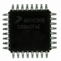
MCHC908GR8ACFAE
Description
IC MCU 8K FLASH 8MHZ 32-LQFP
Manufacturer
Freescale Semiconductor
Series
HC08r
Specifications of MCHC908GR8ACFAE
Core Processor
HC08
Core Size
8-Bit
Speed
8MHz
Connectivity
SCI, SPI
Peripherals
LVD, POR, PWM
Number Of I /o
21
Program Memory Size
7.5KB (7.5K x 8)
Program Memory Type
FLASH
Ram Size
384 x 8
Voltage - Supply (vcc/vdd)
2.7 V ~ 5.5 V
Data Converters
A/D 6x8b
Oscillator Type
Internal
Operating Temperature
-40°C ~ 85°C
Package / Case
32-LQFP
Controller Family/series
HC08
No. Of I/o's
21
Ram Memory Size
384Byte
Cpu Speed
8MHz
No. Of Timers
2
Embedded Interface Type
I2C, SCI, SPI
Rohs Compliant
Yes
Processor Series
HC08G
Core
HC08
Data Bus Width
8 bit
Data Ram Size
384 B
Interface Type
SCI, SPI
Maximum Clock Frequency
8.2 MHz
Number Of Programmable I/os
21
Number Of Timers
3
Maximum Operating Temperature
+ 85 C
Mounting Style
SMD/SMT
Development Tools By Supplier
FSICEBASE, DEMO908GZ60E, M68CBL05CE, M68EML08GPGTE
Minimum Operating Temperature
- 40 C
On-chip Adc
8 bit, 6 Channel
Lead Free Status / RoHS Status
Lead free / RoHS Compliant
Eeprom Size
-
Lead Free Status / Rohs Status
Details
Available stocks
Company
Part Number
Manufacturer
Quantity
Price
Company:

Part Number:
MCHC908GR8ACFAE
Manufacturer:
Freescale Semiconductor
Quantity:
10 000


Low-Power Modes (MODES)
11.3.2 Stop Mode
The break module is inactive in stop mode. A break interrupt causes exit from stop mode and sets the
SBSW bit in the break status register. The STOP instruction does not affect break module register states.
11.4 Central Processor Unit (CPU)
11.4.1 Wait Mode
The WAIT instruction:
11.4.2 Stop Mode
The STOP instruction:
After exiting stop mode, the CPU clock begins running after the oscillator stabilization delay.
11.5 Internal Clock Generator Module (ICG)
11.5.1 Wait Mode
The internal clock generator (ICG) module remains active in wait mode. If enabled, the ICG interrupt to
the CPU can bring the MCU out of wait mode.
In some applications, low power-consumption is desired in wait mode and a high-frequency clock is not
needed. In these applications, reduce power consumption by either selecting a low-frequency external
clock and turn the internal clock generator off or reduce the bus frequency by minimizing the ICG multiplier
factor (N) before executing the WAIT instruction.
11.5.2 Stop Mode
The value of the oscillator enable in stop (OSCENINSTOP) bit in the CONFIG2 register determines the
behavior of the ICG in stop mode. If OSCENINSTOP is low, the ICG is disabled in stop and, upon
execution of the STOP instruction, all ICG activity will cease and the output clocks (CGMXCLK,
CGMOUT, COPCLK, and TBMCLK) will be held low. Power consumption will be minimal.
If OSCENINSTOP is high, the ICG is enabled in stop and activity will continue. This is useful if the
timebase module (TBM) is required to bring the MCU out of stop mode. ICG interrupts will not bring the
MCU out of stop mode in this case.
During stop mode, if OSCENINSTOP is low, several functions in the ICG are affected. The stable bits
(ECGS and ICGS) are cleared, which will enable the external clock stabilization divider upon recovery.
The clock monitor is disabled (CMON = 0) which will also clear the clock monitor interrupt enable (CMIE)
and clock monitor flag (CMF) bits. The CS, ICGON, ECGON, N, TRIM, DDIV, and DSTG bits are
unaffected.
118
•
•
•
•
Clears the interrupt mask (I bit) in the condition code register, enabling interrupts. After exit from
wait mode by interrupt, the I bit remains clear. After exit by reset, the I bit is set.
Disables the CPU clock
Clears the interrupt mask (I bit) in the condition code register, enabling external interrupts. After
exit from stop mode by external interrupt, the I bit remains clear. After exit by reset, the I bit is set.
Disables the CPU clock
MC68HC908GT16 • MC68HC908GT8 • MC68HC08GT16 Data Sheet, Rev. 5.0
Freescale Semiconductor
Related parts for MCHC908GR8ACFAE
Image
Part Number
Description
Manufacturer
Datasheet
Request
R

Part Number:
Description:
Manufacturer:
Freescale Semiconductor, Inc
Datasheet:
Part Number:
Description:
Manufacturer:
Freescale Semiconductor, Inc
Datasheet:
Part Number:
Description:
Manufacturer:
Freescale Semiconductor, Inc
Datasheet:
Part Number:
Description:
Manufacturer:
Freescale Semiconductor, Inc
Datasheet:
Part Number:
Description:
Manufacturer:
Freescale Semiconductor, Inc
Datasheet:
Part Number:
Description:
Manufacturer:
Freescale Semiconductor, Inc
Datasheet:
Part Number:
Description:
Manufacturer:
Freescale Semiconductor, Inc
Datasheet:
Part Number:
Description:
Manufacturer:
Freescale Semiconductor, Inc
Datasheet:
Part Number:
Description:
Manufacturer:
Freescale Semiconductor, Inc
Datasheet:
Part Number:
Description:
Manufacturer:
Freescale Semiconductor, Inc
Datasheet:
Part Number:
Description:
Manufacturer:
Freescale Semiconductor, Inc
Datasheet:
Part Number:
Description:
Manufacturer:
Freescale Semiconductor, Inc
Datasheet:
Part Number:
Description:
Manufacturer:
Freescale Semiconductor, Inc
Datasheet:
Part Number:
Description:
Manufacturer:
Freescale Semiconductor, Inc
Datasheet:
Part Number:
Description:
Manufacturer:
Freescale Semiconductor, Inc
Datasheet: