M38513E4FP#U0 Renesas Electronics America, M38513E4FP#U0 Datasheet - Page 33
M38513E4FP#U0
Manufacturer Part Number
M38513E4FP#U0
Description
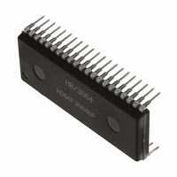
IC 740 MCU ROM 16K 42SSOP
Manufacturer
Renesas Electronics America
Series
740/38000r
Specifications of M38513E4FP#U0
Core Processor
740
Core Size
8-Bit
Speed
8MHz
Connectivity
SIO, UART/USART
Peripherals
PWM, WDT
Number Of I /o
34
Program Memory Size
16KB (16K x 8)
Program Memory Type
OTP
Ram Size
512 x 8
Voltage - Supply (vcc/vdd)
2.7 V ~ 5.5 V
Data Converters
A/D 5x10b
Oscillator Type
External
Operating Temperature
-20°C ~ 85°C
Package / Case
42-SSOP
Package
42SSOP
Family Name
740
Maximum Speed
8 MHz
Operating Supply Voltage
5 V
Data Bus Width
8 Bit
Number Of Programmable I/os
34
Interface Type
I2C-BUS
On-chip Adc
5-chx10-bit
Number Of Timers
4
Lead Free Status / RoHS Status
Contains lead / RoHS non-compliant
Eeprom Size
-


(1) Read-modify-write instruction
The precautions when the read-modify-write instruction such as
SEB, CLB etc. is executed for each register of the multi-master
I
• I
• I
• I
• I
• I
• I
(2) START condition generating procedure using multi-master
1. Procedure example (The necessary conditions of the generat-
2. Use “Branch on Bit Set” of “BBS 5, $002D, –” for the BB flag
3. Use “STA $2B, STX $2B” or “STY $2B” of the zero page ad-
4. Execute the branch instruction of above 2 and the store instruc-
30
2
C-BUS interface are described below.
When executing the read-modify-write instruction for this regis-
ter during transfer, data may become a value not intended.
When the read-modify-write instruction is executed for this regis-
ter at detecting the STOP condition, data may become a value
not intended. It is because H/W changes the read/write bit
(RBW) at the above timing.
Do not execute the read-modify-write instruction for this register
because all bits of this register are changed by H/W.
When the read-modify-write instruction is executed for this regis-
ter at detecting the START condition or at completing the byte
transfer, data may become a value not intended. Because H/W
changes the bit counter (BC0-BC2) at the above timing.
The read-modify-write instruction can be executed for this regis-
ter.
0030
The read-modify-write instruction can be executed for this regis-
ter.
Precautions when using multi-master I
BUS interface
ing procedure are described as the following 2 to 5.
cess)
BUSFREE:
BUSBUSY:
confirming and branch process.
dressing instruction for writing the slave address value to the
I
tion of above 3 continuously shown the above procedure
example.
2
2
2
2
2
2
2
C data shift register (S0: address 002B
C address register (S0D: address 002C
C status register (S1: address 002D
C control register (S1D: address 002E
C clock control register (S2: address 002F
C START/STOP condition control register (S2D: address
LDA —
SEI
BBS 5, S1, BUSBUSY (BB flag confirming and branch pro-
STA S0
LDM #$F0, S1
CLI
CLI
C data shift register.
: :
: :
: :
16
)
(Taking out of slave address value)
(Interrupt disabled)
(Writing of slave address value)
(Trigger of START condition generating)
(Interrupt enabled)
(Interrupt enabled)
16
)
16
16
16
)
)
)
16
)
2
C-
5. Disable interrupts during the following three process steps:
(3) RESTART condition generating procedure
1. Procedure example (The necessary conditions of the generat-
2. Select the slave receive mode when the PIN bit is “0.” Do not
3. The S
4. Disable interrupts during the following two process steps:
(4) Writing to I
Do not execute an instruction to set the PIN bit to “1” from “0” and
an instruction to set the MST and TRX bits to “0” from “1” simulta-
neously. It is because it may enter the state that the S
released and the S
cycle. Do not execute an instruction to set the MST and TRX bits
to “0” from “1” simultaneously when the PIN bit is “1.” It is because
it may become the same as above.
(5) Process of after STOP condition generating
Do not write data in the I
tus register S1 until the bus busy flag BB becomes “0” after
generating the STOP condition in the master mode. It is because
the STOP condition waveform might not be normally generated.
Reading to the above registers do not have the problem.
• Writing of slave address value
• Trigger of RESTART condition generating
• BB flag confirming
• Writing of slave address value
• Trigger of START condition generating
When the condition of the BB flag is bus busy, enable interrupts
immediately.
ing procedure are described as the following 2 to 4.)
Execute the following procedure when the PIN bit is “0.”
write “1” to the PIN bit. Neither “0” nor “1” is specified for the
writing to the BB bit.
The TRX bit becomes “0” and the S
the I
LDM #$00, S1
LDA —
SEI
STA S0
LDM #$F0, S1
CLI
: :
: :
2
C data shift register.
CL
SINGLE-CHIP 8-BIT CMOS MICROCOMPUTER
pin is released by writing the slave address value to
2
C status register
DA
MITSUBISHI MICROCOMPUTERS
pin is released after about one machine
2
C data shift register S0 and the I
(Select slave receive mode)
(Taking out of slave address value)
(Interrupt disabled)
(Writing of slave address value)
(Trigger of RESTART condition generating)
(Interrupt enabled)
(Built-in 16 KB ROM)
DA
pin is released.
3851 Group
CL
2
C sta-
pin is
Related parts for M38513E4FP#U0
Image
Part Number
Description
Manufacturer
Datasheet
Request
R

Part Number:
Description:
KIT STARTER FOR M16C/29
Manufacturer:
Renesas Electronics America
Datasheet:

Part Number:
Description:
KIT STARTER FOR R8C/2D
Manufacturer:
Renesas Electronics America
Datasheet:

Part Number:
Description:
R0K33062P STARTER KIT
Manufacturer:
Renesas Electronics America
Datasheet:

Part Number:
Description:
KIT STARTER FOR R8C/23 E8A
Manufacturer:
Renesas Electronics America
Datasheet:

Part Number:
Description:
KIT STARTER FOR R8C/25
Manufacturer:
Renesas Electronics America
Datasheet:

Part Number:
Description:
KIT STARTER H8S2456 SHARPE DSPLY
Manufacturer:
Renesas Electronics America
Datasheet:

Part Number:
Description:
KIT STARTER FOR R8C38C
Manufacturer:
Renesas Electronics America
Datasheet:

Part Number:
Description:
KIT STARTER FOR R8C35C
Manufacturer:
Renesas Electronics America
Datasheet:

Part Number:
Description:
KIT STARTER FOR R8CL3AC+LCD APPS
Manufacturer:
Renesas Electronics America
Datasheet:
Part Number:
Description:
KIT STARTER FOR RX610
Manufacturer:
Renesas Electronics America
Datasheet:

Part Number:
Description:
KIT STARTER FOR R32C/118
Manufacturer:
Renesas Electronics America
Datasheet:

Part Number:
Description:
KIT DEV RSK-R8C/26-29
Manufacturer:
Renesas Electronics America
Datasheet:

Part Number:
Description:
KIT STARTER FOR SH7124
Manufacturer:
Renesas Electronics America
Datasheet:

Part Number:
Description:
KIT STARTER FOR H8SX/1622
Manufacturer:
Renesas Electronics America
Datasheet:

Part Number:
Description:
KIT DEV FOR SH7203
Manufacturer:
Renesas Electronics America
Datasheet: