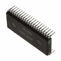
M38513E4FP#U0 Renesas Electronics America, M38513E4FP#U0 Datasheet - Page 42

M38513E4FP#U0
Manufacturer Part Number
M38513E4FP#U0
Description
IC 740 MCU ROM 16K 42SSOP
Manufacturer
Renesas Electronics America
Series
740/38000r
Specifications of M38513E4FP#U0
Core Processor
740
Core Size
8-Bit
Speed
8MHz
Connectivity
SIO, UART/USART
Peripherals
PWM, WDT
Number Of I /o
34
Program Memory Size
16KB (16K x 8)
Program Memory Type
OTP
Ram Size
512 x 8
Voltage - Supply (vcc/vdd)
2.7 V ~ 5.5 V
Data Converters
A/D 5x10b
Oscillator Type
External
Operating Temperature
-20°C ~ 85°C
Package / Case
42-SSOP
Package
42SSOP
Family Name
740
Maximum Speed
8 MHz
Operating Supply Voltage
5 V
Data Bus Width
8 Bit
Number Of Programmable I/os
34
Interface Type
I2C-BUS
On-chip Adc
5-chx10-bit
Number Of Timers
4
Lead Free Status / RoHS Status
Contains lead / RoHS non-compliant
Eeprom Size
-
Fig. 48 State transitions of system clock
Notes 1 : Switch the mode by the allows shown between the mode blocks. (Do not switch between the modes directly without an allow.)
2 : The all modes can be switched to the stop mode or the wait mode and return to the source mode when the stop mode or the wait mode is
3 : Timer operates in the wait mode.
4 : When bit 0 of MISRG is “0” and the stop mode is ended, a delay of approximately 1 ms occurs by connecting timer 1 in middle/high-speed
5 : When bit 0 of MISRG is “0” and the stop mode is ended, the following is performed.
6 : Wait until oscillation stabilizes after oscillating the main clock X
7 : The example assumes that 8 MHz is being applied to the X
C M
C M
C M
C M
C M
C M
C M
C M
M i d d l e - s p e e d m o d e
7
6
5
4
ended.
mode.
(1) After the clock is restarted, a delay of approximately 256 ms occurs in low-speed mode if Timer 12 count source selection bit is “0”.
(2) After the clock is restarted, a delay of approximately 16 ms occurs in low-speed mode if Timer 12 count source selection bit is “1”.
mode.
M i d d l e - s p e e d m o d e
7
6
5
4
= 0
= 1
= 0 ( 8 M H z o s c i l l a t i n g )
= 1 ( 3 2 k H z o s c i l l a t i n g )
= 0
= 1
= 0 ( 8 M H z o s c i l l a t i n g )
= 0 ( 3 2 k H z s t o p p e d )
( f ( ) = 1 M H z )
( f ( ) = 1 M H z )
R e s e t
C M
“ 1 ”
CM
“1”
6
6
“ 0 ”
“0”
CM
CM
CM
CM
C M
C M
C M
C M
C M
C M
C M
C M
C M
C M
C M
C M
7
6
5
4
7
6
5
4
7
6
5
4
=1
=0
=0(8 MHz oscillating)
=1(32 kHz oscillating)
7
6
5
4
= 0
= 0
= 0 ( 8 M H z o s c i l l a t i n g )
= 1 ( 3 2 k H z o s c i l l a t i n g )
= 1
= 0
= 1 ( 8 M H z s t o p p e d )
= 1 ( 3 2 k H z o s c i l l a t i n g )
H i g h - s p e e d m o d e
H i g h - s p e e d m o d e
= 0
= 0
= 0 ( 8 M H z o s c i l l a t i n g )
= 0 ( 3 2 k H z s t o p p e d )
L o w - s p e e d m o d e
Low-speed mode
( f ( ) = 4 M H z )
( f ( ) = 1 6 k H z )
( f ( ) = 4 M H z )
(f( )=16 kHz)
IN
pin and 32 kHz to the X
IN
before the switching from the low-speed mode to middle/high-speed
b 7
SINGLE-CHIP 8-BIT CMOS MICROCOMPUTER
CIN
b 4
pin.
CM
CM
CM
4
5
7
MITSUBISHI MICROCOMPUTERS
indicates the internal clock.
, CM
: Port Xc switch bit
: Main clock (X
b7 b6
0 : I/O port function (stop oscillating)
1 : X
0 : Operating
1 : Stopped
0
0
1
1
6
: Main clock division ratio selection bits
0 :
1 :
0 :
1 : Not available
CIN
CPU mode register
(CPUM : address 003B
-X
= f(X
= f(X
= f(X
COUT
(Built-in 16 KB ROM)
IN
oscillating function
IN
IN
CIN
- X
)/2 ( High-speed mode)
)/8 (Middle-speed mode)
)/2 (Low-speed mode)
OUT
) stop bit
3851 Group
16
)
39


