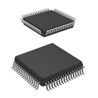
HD6473228F10V Renesas Electronics America, HD6473228F10V Datasheet - Page 227

HD6473228F10V
Manufacturer Part Number
HD6473228F10V
Description
MCU 5V 32K,PB-FREE 64-QFP
Manufacturer
Renesas Electronics America
Series
H8® H8/325r
Datasheet
1.HD6413238F10.pdf
(301 pages)
Specifications of HD6473228F10V
Core Processor
H8/300
Core Size
8-Bit
Speed
10MHz
Connectivity
SCI, UART/USART
Number Of I /o
53
Program Memory Size
8KB (8K x 8)
Program Memory Type
OTP
Ram Size
256 x 8
Voltage - Supply (vcc/vdd)
4.5 V ~ 5.5 V
Oscillator Type
External
Operating Temperature
-20°C ~ 75°C
Package / Case
64-QFP
Lead Free Status / RoHS Status
Lead free / RoHS Compliant
Eeprom Size
-
Data Converters
-
Peripherals
-
Available stocks
Company
Part Number
Manufacturer
Quantity
Price
Company:
Part Number:
HD6473228F10V
Manufacturer:
Renesas Electronics America
Quantity:
10 000
- Current page: 227 of 301
- Download datasheet (2Mb)
12.4.1 Transition to Software Standby Mode
To enter the software standby mode, set the standby bit (SSBY) in the system control register
(SYSCR) to 1, then execute the SLEEP instruction.
12.4.2 Exit from Software Standby Mode
The chip can be brought out of the software standby mode by an input at one of seven pins: NMI,
IRQ
, IRQ
, IRQ
, IS, RES, or STBY.
0
1
2
(1) Recovery by External Interrupt: When an NMI, IRQ
, IRQ
, IRQ
, or input strobe (ISI)
0
1
2
interrupt request signal is received, the clock oscillator begins operating. After the waiting time set
in the system control register (bits STS2 to STS0), clock pulses are supplied to the CPU and on-
chip supporting modules. The CPU executes the interrupt-handling sequence for the requested
interrupt, then returns to the instruction after the SLEEP instruction. The SSBY bit is not cleared.
See Section 12.2, System Control Register: Power-Down Control Bits for information about the
STS bits.
(2) Recovery by RES Pin: When the RES pin goes low, the clock oscillator starts. Next, when
the RES pin goes high, the CPU begins executing the reset sequence. The SSBY bit is cleared to 0.
The RES pin must be held low long enough for the clock to stabilize.
(3) Recovery by STBY Pin: When the STBY pin goes low, the chip exits from the software
standby mode to the hardware standby mode.
12.4.3 Sample Application of Software Standby Mode
In this example the chip enters the software standby mode when NMI goes low and exits when
NMI goes high, as shown in figure 12-1.
223
Related parts for HD6473228F10V
Image
Part Number
Description
Manufacturer
Datasheet
Request
R

Part Number:
Description:
KIT STARTER FOR M16C/29
Manufacturer:
Renesas Electronics America
Datasheet:

Part Number:
Description:
KIT STARTER FOR R8C/2D
Manufacturer:
Renesas Electronics America
Datasheet:

Part Number:
Description:
R0K33062P STARTER KIT
Manufacturer:
Renesas Electronics America
Datasheet:

Part Number:
Description:
KIT STARTER FOR R8C/23 E8A
Manufacturer:
Renesas Electronics America
Datasheet:

Part Number:
Description:
KIT STARTER FOR R8C/25
Manufacturer:
Renesas Electronics America
Datasheet:

Part Number:
Description:
KIT STARTER H8S2456 SHARPE DSPLY
Manufacturer:
Renesas Electronics America
Datasheet:

Part Number:
Description:
KIT STARTER FOR R8C38C
Manufacturer:
Renesas Electronics America
Datasheet:

Part Number:
Description:
KIT STARTER FOR R8C35C
Manufacturer:
Renesas Electronics America
Datasheet:

Part Number:
Description:
KIT STARTER FOR R8CL3AC+LCD APPS
Manufacturer:
Renesas Electronics America
Datasheet:

Part Number:
Description:
KIT STARTER FOR RX610
Manufacturer:
Renesas Electronics America
Datasheet:

Part Number:
Description:
KIT STARTER FOR R32C/118
Manufacturer:
Renesas Electronics America
Datasheet:

Part Number:
Description:
KIT DEV RSK-R8C/26-29
Manufacturer:
Renesas Electronics America
Datasheet:

Part Number:
Description:
KIT STARTER FOR SH7124
Manufacturer:
Renesas Electronics America
Datasheet:

Part Number:
Description:
KIT STARTER FOR H8SX/1622
Manufacturer:
Renesas Electronics America
Datasheet:

Part Number:
Description:
KIT DEV FOR SH7203
Manufacturer:
Renesas Electronics America
Datasheet:


