HD6473228F10V Renesas Electronics America, HD6473228F10V Datasheet - Page 65
HD6473228F10V
Manufacturer Part Number
HD6473228F10V
Description
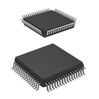
MCU 5V 32K,PB-FREE 64-QFP
Manufacturer
Renesas Electronics America
Series
H8® H8/325r
Datasheet
1.HD6413238F10.pdf
(301 pages)
Specifications of HD6473228F10V
Core Processor
H8/300
Core Size
8-Bit
Speed
10MHz
Connectivity
SCI, UART/USART
Number Of I /o
53
Program Memory Size
8KB (8K x 8)
Program Memory Type
OTP
Ram Size
256 x 8
Voltage - Supply (vcc/vdd)
4.5 V ~ 5.5 V
Oscillator Type
External
Operating Temperature
-20°C ~ 75°C
Package / Case
64-QFP
Lead Free Status / RoHS Status
Lead free / RoHS Compliant
Eeprom Size
-
Data Converters
-
Peripherals
-
Available stocks
Company
Part Number
Manufacturer
Quantity
Price
Company:

Part Number:
HD6473228F10V
Manufacturer:
Renesas Electronics America
Quantity:
10 000


3.6.3 Power-Down State
The power-down state includes three modes: the sleep mode, the software standby mode, and the
hardware standby mode.
(1) Sleep Mode: The sleep mode is entered when a SLEEP instruction is executed. The CPU
halts, but CPU register contents remain unchanged and the on-chip supporting modules continue to
function.
When an interrupt or reset signal is received, the CPU returns through the exception-handling state
to the program execution state.
(2) Software Standby Mode: The software standby mode is entered if the SLEEP instruction is
executed while the SSBY (Software Standby) bit in the system control register (SYSCR) is set.
The CPU and all on-chip supporting modules halt. The on-chip supporting modules are initialized,
but the contents of the on-chip RAM and CPU registers remain unchanged. I/O port outputs also
remain unchanged.
(3) Hardware Standby Mode: The hardware standby mode is entered when the input at the
STBY pin goes Low. All chip functions halt, including I/O port output. The on-chip supporting
modules are initialized, but on-chip RAM contents are held.
See section 12, “Power-Down State” for further information.
3.7 Access Timing and Bus Cycle
The CPU is driven by the system clock (Ø). The period from one rising edge of the system clock to
the next is referred to as a “state.”
Memory access is performed in a two-or three-state bus cycle as described below. For more
detailed timing diagrams of the bus cycles, see section 15, “Electrical Specifications.”
3.7.1 Access to On-Chip Memory (RAM and ROM)
On-chip ROM and RAM are accessed in a cycle of two states designated T
and T
. Either byte or
1
2
word data can be accessed, via a 16-bit data bus. Figure 3-13 shows the on-chip memory access
cycle. Figure 3-14 shows the associated pin states.
56
Related parts for HD6473228F10V
Image
Part Number
Description
Manufacturer
Datasheet
Request
R

Part Number:
Description:
KIT STARTER FOR M16C/29
Manufacturer:
Renesas Electronics America
Datasheet:

Part Number:
Description:
KIT STARTER FOR R8C/2D
Manufacturer:
Renesas Electronics America
Datasheet:

Part Number:
Description:
R0K33062P STARTER KIT
Manufacturer:
Renesas Electronics America
Datasheet:

Part Number:
Description:
KIT STARTER FOR R8C/23 E8A
Manufacturer:
Renesas Electronics America
Datasheet:

Part Number:
Description:
KIT STARTER FOR R8C/25
Manufacturer:
Renesas Electronics America
Datasheet:

Part Number:
Description:
KIT STARTER H8S2456 SHARPE DSPLY
Manufacturer:
Renesas Electronics America
Datasheet:

Part Number:
Description:
KIT STARTER FOR R8C38C
Manufacturer:
Renesas Electronics America
Datasheet:

Part Number:
Description:
KIT STARTER FOR R8C35C
Manufacturer:
Renesas Electronics America
Datasheet:

Part Number:
Description:
KIT STARTER FOR R8CL3AC+LCD APPS
Manufacturer:
Renesas Electronics America
Datasheet:
Part Number:
Description:
KIT STARTER FOR RX610
Manufacturer:
Renesas Electronics America
Datasheet:

Part Number:
Description:
KIT STARTER FOR R32C/118
Manufacturer:
Renesas Electronics America
Datasheet:

Part Number:
Description:
KIT DEV RSK-R8C/26-29
Manufacturer:
Renesas Electronics America
Datasheet:

Part Number:
Description:
KIT STARTER FOR SH7124
Manufacturer:
Renesas Electronics America
Datasheet:

Part Number:
Description:
KIT STARTER FOR H8SX/1622
Manufacturer:
Renesas Electronics America
Datasheet:

Part Number:
Description:
KIT DEV FOR SH7203
Manufacturer:
Renesas Electronics America
Datasheet: