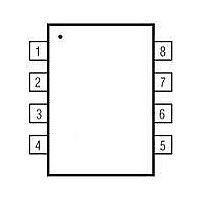
MAXQ610A-0000+ Maxim Integrated Products, MAXQ610A-0000+ Datasheet - Page 7

MAXQ610A-0000+
Manufacturer Part Number
MAXQ610A-0000+
Description
IC MCU 16BIT 64K IR MOD 32TQFN
Manufacturer
Maxim Integrated Products
Series
MAXQ™r
Datasheets
1.MAXQ610A-0000.pdf
(28 pages)
2.MAXQ610A-0000.pdf
(29 pages)
3.MAXQ610A-0000.pdf
(23 pages)
Specifications of MAXQ610A-0000+
Core Processor
RISC
Core Size
16-Bit
Speed
12MHz
Connectivity
SPI, UART/USART
Peripherals
Brown-out Detect/Reset, Infrared, Power-Fail, POR, WDT
Number Of I /o
20
Program Memory Size
64KB (64K x 8)
Program Memory Type
FLASH
Ram Size
2K x 8
Voltage - Supply (vcc/vdd)
1.7 V ~ 3.6 V
Oscillator Type
Internal
Operating Temperature
0°C ~ 70°C
Package / Case
32-TQFN Exposed Pad
Processor Series
MAXQ610
Core
RISC
Data Bus Width
16 bit
Data Ram Size
2 KB
Interface Type
SPI, USART
Maximum Clock Frequency
12 MHz
Number Of Timers
4
Operating Supply Voltage
1.7 V to 3.6 V
Maximum Operating Temperature
+ 70 C
Mounting Style
SMD/SMT
Minimum Operating Temperature
0 C
Controller Family/series
MAXQ
No. Of I/o's
24
Ram Memory Size
2048Byte
Cpu Speed
12MHz
No. Of Timers
2
Embedded Interface Type
JTAG, SPI, USART
Rohs Compliant
Yes
Number Of Programmable I/os
32
Development Tools By Supplier
MAXQ610-KIT
Package
32TQFN EP
Family Name
MAXQ
Maximum Speed
12 MHz
Lead Free Status / RoHS Status
Lead free / RoHS Compliant
Eeprom Size
-
Data Converters
-
Lead Free Status / Rohs Status
Lead free / RoHS Compliant
Other names
90-M6800+B01
14, 30
PIN
1–8
13
—
29
17
18
31
32
16-Bit Microcontroller with Infrared Module
TBA0, TBA1;
TBB0, TBB1;
INT8–INT15
P0.0–P0.7;
REGOUT
HFXOUT
_______________________________________________________________________________________
IRTXM;
RESET
NAME
HFXIN
(GND)
IRRX
IRTX
V
EP
DD
Supply Voltage
Regulator Capacitor. This pin must be connected to ground through a 1.0μF external ceramic-
chip capacitor in series with a 2 to 10 resistor. The capacitor must be placed as close to this
pin as
this pin.
Exposed Pad/Ground. The GND contact is through the exposed paddle located on the
underside of the package. It must be directly connected to the ground plane.
Digital, Active-Low, Reset Input/Output. The CPU is held in reset when this pin is low and
begins executing from the reset vector when released. The pin includes pullup current source
and should be driven by an open-drain, external source capable of sinking in excess of 4mA.
This pin is driven low as an output when an internal reset condition occurs.
High-Frequency Crystal Input. Connect an external crystal or resonator between HFXIN and
HFXOUT as the high-frequency system clock. Alternatively, HFXIN is the input for an external,
high-frequency clock source when HFXOUT is floating.
IR Transmit Output. IR transmit pin capable of sinking 25mA. This pin defaults to a high-
impedance input with the weak pullup disabled during all forms of reset. Software must
configure this pin after release from reset to remove the high-impedance input condition.
IR Receive Input. IR receive pin. This pin defaults to a high-impedance input with the weak
pullup disabled during all forms of reset. Software must configure this pin after release from
reset to remove the high-impedance input condition.
General-Purpose, Digital, I/O, Type-D Port. These port pins function as bidirectional I/O pins.
All port pins default to high-impedance mode after a reset. Software must configure these pins
after release from reset to remove the high-impedance input condition. All alternate functions
must be enabled from software. Port 0 can optionally be defined with INT8–INT15.
GENERAL-PURPOSE I/O AND SPECIAL FUNCTION PINS
possible.
PIN
1
2
3
4
5
6
7
8
No other external devices other than the capacitor should be connected to
IR FUNCTION PINS
POWER PINS
RESET PINS
CLOCK PINS
FUNCTION
PORT
P0.0
P0.1
P0.2
P0.3
P0.4
P0.5
P0.6
P0.7
SPECIAL FUNCTION
Pin Description
TBA0/TBA1/INT13
TBB0/INT14
TBB1/INT15
IRTXM/INT8
INT10
INT11
INT12
INT9
7


