MAX6478BL33AD3+T Maxim Integrated Products, MAX6478BL33AD3+T Datasheet - Page 12
MAX6478BL33AD3+T
Manufacturer Part Number
MAX6478BL33AD3+T
Description
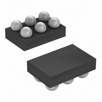
IC LDO REG 300MA 3.3V/ADJ 6-UCSP
Manufacturer
Maxim Integrated Products
Datasheet
1.MAX6469TA15BD3T.pdf
(20 pages)
Specifications of MAX6478BL33AD3+T
Regulator Topology
Positive Fixed or Adjustable
Voltage - Output
3.3V, 1.25 ~ 5.5 V
Voltage - Input
2.5 ~ 5.5 V
Voltage - Dropout (typical)
0.114V @ 300mA, -
Number Of Regulators
1
Current - Output
300mA (Min)
Current - Limit (min)
450mA
Operating Temperature
-40°C ~ 85°C
Mounting Type
Surface Mount
Package / Case
6-UCSP®
Number Of Outputs
1
Polarity
Positive
Input Voltage Max
5.5 V
Output Voltage
1.2 V to 5 V, 3.3 V
Output Type
Adjustable, Fixed
Dropout Voltage (max)
0.032 V at 50 mA
Output Current
0.3 A
Line Regulation
0.09 % / V
Load Regulation
0.2 %
Voltage Regulation Accuracy
1.1 %
Maximum Power Dissipation
840 mW
Maximum Operating Temperature
+ 85 C
Mounting Style
SMD/SMT
Minimum Operating Temperature
- 40 C
Reference Voltage
1.229 V
Lead Free Status / RoHS Status
Lead free / RoHS Compliant


300mA LDO Linear Regulators with Internal
Microprocessor Reset Circuit
For the SOT23 package, any pin except the SET pin
can be used as a heatsink. If the SET pin is used as a
heatsink, excessive parasitic capacitance can affect
stability. For the TDFN package, the exposed metal
pad on the back side of a package connects to GND of
the chip. This metal pad can be used as a heatsink.
For general UCSP package information and PC layout
considerations, refer to Maxim Application Note: Wafer-
Level Chip-Scale Package .
Table 1. Output Voltage Suffix Guide
Note: Factory-trimmed custom output voltages may be avail-
able; contact factory for availability.
12
______________________________________________________________________________________
SUFFIX
285
15
16
17
18
19
20
21
22
23
24
25
26
27
28
29
30
31
32
33
Power Dissipation Consideration
UCSP Consideration
VOLTAGE (V)
OUTPUT
2.85
1.5
1.6
1.7
1.8
1.9
2.0
2.1
2.2
2.3
2.4
2.5
2.6
2.7
2.8
2.9
3.0
3.1
3.2
3.3
The chip-scale package (UCSP) represents a unique
packaging form factor that might not perform equally to
a packaged product through traditional mechanical
reliability tests. CSP reliability is integrally linked to the
user’s assembly methods, circuit-board material, and
usage environment. The user should closely review
these areas when considering a CSP package.
Performance through operating life test and moisture
resistance remains uncompromised, because it is pri-
marily determined by the wafer-fabrication process.
Mechanical stress performance is a greater considera-
tion for a CSP package. CSPs are attached through
direct solder contact to the user’s PC board, forgoing
the inherent stress relief of a packaged product’s lead
frame. Solder-joint contact integrity must be considered.
Information on Maxim’s qualification plan, test data, and
recommendations are detailed in the UCSP application
note on Maxim’s website at www.maxim-ic.com.
Table 2. Reset Threshold Accuracy Guide
Table 3. Reset Timeout Delay Guide
SUFFIX
SUFFIX
D1
D2
D3
D4
A
B
TIMEOUT PERIOD (ms)
UCSP Reliability
MINIMUM RESET
TOLERANCE (%)
V
OUT
1200
-12.5
150
2.5
-7.5
20
RESET
Related parts for MAX6478BL33AD3+T
Image
Part Number
Description
Manufacturer
Datasheet
Request
R

Part Number:
Description:
MAX7528KCWPMaxim Integrated Products [CMOS Dual 8-Bit Buffered Multiplying DACs]
Manufacturer:
Maxim Integrated Products
Datasheet:
Part Number:
Description:
Single +5V, fully integrated, 1.25Gbps laser diode driver.
Manufacturer:
Maxim Integrated Products
Datasheet:
Part Number:
Description:
Single +5V, fully integrated, 155Mbps laser diode driver.
Manufacturer:
Maxim Integrated Products
Datasheet:
Part Number:
Description:
VRD11/VRD10, K8 Rev F 2/3/4-Phase PWM Controllers with Integrated Dual MOSFET Drivers
Manufacturer:
Maxim Integrated Products
Datasheet:
Part Number:
Description:
Highly Integrated Level 2 SMBus Battery Chargers
Manufacturer:
Maxim Integrated Products
Datasheet:
Part Number:
Description:
Current Monitor and Accumulator with Integrated Sense Resistor; ; Temperature Range: -40°C to +85°C
Manufacturer:
Maxim Integrated Products
Part Number:
Description:
TSSOP 14/A�/RS-485 Transceivers with Integrated 100O/120O Termination Resis
Manufacturer:
Maxim Integrated Products
Part Number:
Description:
TSSOP 14/A�/RS-485 Transceivers with Integrated 100O/120O Termination Resis
Manufacturer:
Maxim Integrated Products
Part Number:
Description:
QFN 16/A�/AC-DC and DC-DC Peak-Current-Mode Converters with Integrated Step
Manufacturer:
Maxim Integrated Products
Part Number:
Description:
TDFN/A/65V, 1A, 600KHZ, SYNCHRONOUS STEP-DOWN REGULATOR WITH INTEGRATED SWI
Manufacturer:
Maxim Integrated Products
Part Number:
Description:
Integrated Temperature Controller f
Manufacturer:
Maxim Integrated Products
Part Number:
Description:
SOT23-6/I�/45MHz to 650MHz, Integrated IF VCOs with Differential Output
Manufacturer:
Maxim Integrated Products
Part Number:
Description:
SOT23-6/I�/45MHz to 650MHz, Integrated IF VCOs with Differential Output
Manufacturer:
Maxim Integrated Products
Part Number:
Description:
EVALUATION KIT/2.4GHZ TO 2.5GHZ 802.11G/B RF TRANSCEIVER WITH INTEGRATED PA
Manufacturer:
Maxim Integrated Products
Part Number:
Description:
QFN/E/DUAL PCIE/SATA HIGH SPEED SWITCH WITH INTEGRATED BIAS RESISTOR
Manufacturer:
Maxim Integrated Products
Datasheet: