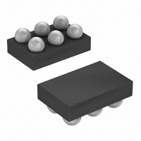
MAX6478BL33AD3+T Maxim Integrated Products, MAX6478BL33AD3+T Datasheet - Page 9

MAX6478BL33AD3+T
Manufacturer Part Number
MAX6478BL33AD3+T
Description
IC LDO REG 300MA 3.3V/ADJ 6-UCSP
Manufacturer
Maxim Integrated Products
Datasheet
1.MAX6469TA15BD3T.pdf
(20 pages)
Specifications of MAX6478BL33AD3+T
Regulator Topology
Positive Fixed or Adjustable
Voltage - Output
3.3V, 1.25 ~ 5.5 V
Voltage - Input
2.5 ~ 5.5 V
Voltage - Dropout (typical)
0.114V @ 300mA, -
Number Of Regulators
1
Current - Output
300mA (Min)
Current - Limit (min)
450mA
Operating Temperature
-40°C ~ 85°C
Mounting Type
Surface Mount
Package / Case
6-UCSP®
Number Of Outputs
1
Polarity
Positive
Input Voltage Max
5.5 V
Output Voltage
1.2 V to 5 V, 3.3 V
Output Type
Adjustable, Fixed
Dropout Voltage (max)
0.032 V at 50 mA
Output Current
0.3 A
Line Regulation
0.09 % / V
Load Regulation
0.2 %
Voltage Regulation Accuracy
1.1 %
Maximum Power Dissipation
840 mW
Maximum Operating Temperature
+ 85 C
Mounting Style
SMD/SMT
Minimum Operating Temperature
- 40 C
Reference Voltage
1.229 V
Lead Free Status / RoHS Status
Lead free / RoHS Compliant
The MAX6469–MAX6484 are ultra-low, quiescent cur-
rent, low-dropout linear regulators with an integrated
microprocessor reset circuit. These devices guarantee
300mA (min) drive capabilities and are available with
preset output voltages in 100mV increments between
+1.5V and +3.3V. The internal reset circuit monitors the
regulator output voltage and asserts the reset output
when the regulator output is below the microprocessor
supply tolerance.
The regulator core operates with +2.5V to +5.5V input
voltage range. The output voltage is offered in 100mV
increments between +1.5V and +3.3V (contact factory
for other output voltage options). The MAX6469–
MAX6472/MAX6477–MAX6480 offer an adjustable out-
put voltage implemented with an external resistor-
divider network between OUT, SET, and GND (Figure
1). SET must be connected to either GND for fixed
V
MAX6469–MAX6472/MAX6477–MAX6480 automatically
determine the feedback path depending on the con-
nection of SET. The Typical Operating Circuit shows a
typical connection for the MAX6469. OUT is an internal-
ly regulated low-dropout (LDO) linear regulator that
powers a microprocessor.
The reset supervisor circuit is fully integrated in the
MAX6469–MAX6484 and uses the same reference volt-
age as the regulator. Two supply tolerance reset
thresholds, -7.5% and -12.5%, are provided for each
type of device.
-7.5% Reset: Reset does not assert until the regulator
output voltage is at least -5% out of tolerance and
always asserts before the regulator output voltage is
-10% out of tolerance.
-12.5% Reset: Reset does not assert until the regulator
output voltage is at least -10% out of tolerance and
always asserts before the regulator output voltage is
-15% out of tolerance.
A µP’s reset input starts the µP in a known state. The
MAX6469–MAX6484 µP supervisory circuits assert
RESET during power-up, power-down, and brownout
conditions. RESET asserts when the input voltage is
below the undervoltage lockout threshold. RESET
asserts when V
remains asserted for at least the minimum selected reset
timeout period (t
undervoltage lockout threshold and V
OUT
or to an external divider for adjustable V
300mA LDO Linear Regulators with Internal
OUT
RP
_______________________________________________________________________________________
, Table 3) after V
is below the reset threshold and
Detailed Description
IN
Reset Circuit
OUT
rises above the
RESET Output
Regulator
rises above
OUT
Microprocessor Reset Circuit
. The
the reset threshold. RESET asserts when MR is pulled
low (MAX6471–MAX6474/MAX6479–MAX6482). RESET
asserts when SHDN is pulled low (MAX6469/
MAX6470/MAX6473–MAX6478/MAX6481–MAX6484).
SHDN allows the regulator to shut down, thereby reduc-
ing the total I
vides a digitally controlled active-low shutdown. In
shutdown mode, the pass transistor, control circuit, and
reference turn off to reduce the supply current to below
0.1µA. Connect SHDN to IN for normal operation.
Many µP-based products require manual reset capabil-
ity, allowing the operator, a test technician, or external
logic circuitry to initiate a reset. A logic low on MR
asserts reset while the regulator output voltage is still
within tolerance.
Reset remains asserted while MR is low and for the
reset timeout period (t
MR input has an internal pullup of 40kΩ (typ) to OUT.
MR can be driven with TTL/CMOS logic levels or with
open-drain/collector outputs. Connect a normally open
switch from MR to GND to create a manual reset func-
tion; external debounce circuitry is not required. If MR
is driven from long cables or the device is used in a
noisy environment, connect a 0.1µF capacitor from MR
to GND to provide additional noise immunity.
The feedback input (FB) connects to an internal resistor-
divider network ( Functional Diagram ). FB is not internally
connected to V
Figure 1. Adjustable Output Voltage Configuration
(MAX6469/MAX6470/MAX6473–MAX6478/MAX6481–
( ) ARE FOR MAX6471/MAX6472/MAX6479/MAX6480 ONLY
(MAX6471–MAX6474/MAX6479–MAX6482 only)
(MAX6475/MAX6476/MAX6483/MAX6484 only)
MANUAL
RESET
IN
consumption of the device. SHDN pro-
2.5V TO 5.5V
OUT
(MR)
, and as a result can be used to
MAX6469–MAX6472
MAX6477–MAX6480
RP
) after MR returns high. The
GND
IN
OUT
SET
Manual Reset Input
Feedback Input
MAX6484 only)
R1
R2
Shutdown
C
OUT
9


