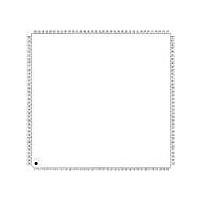
XR17D158CV-F Exar Corporation, XR17D158CV-F Datasheet - Page 41

XR17D158CV-F
Manufacturer Part Number
XR17D158CV-F
Description
IC UART PCI BUS OCTAL 144LQFP
Manufacturer
Exar Corporation
Type
IrDA or RS- 485r
Datasheet
1.XR17D158CV-F.pdf
(73 pages)
Specifications of XR17D158CV-F
Number Of Channels
8
Package / Case
144-LQFP
Features
*
Fifo's
64 Byte
Protocol
RS485
Voltage - Supply
3.3V, 5V
With Auto Flow Control
Yes
With Irda Encoder/decoder
Yes
With False Start Bit Detection
Yes
With Modem Control
Yes
Mounting Type
Surface Mount
Data Rate
6.25 Mbps
Supply Voltage (max)
5.5 V
Supply Voltage (min)
4.5 V
Supply Current
5 mA
Maximum Operating Temperature
+ 70 C
Minimum Operating Temperature
0 C
Mounting Style
SMD/SMT
Operating Supply Voltage
5 V
No. Of Channels
8
Uart Features
Tx/Rx FIFO Counters
Supply Voltage Range
3V To 5.5V
Operating Temperature Range
0°C To +70°C
Digital Ic Case Style
LQFP
No. Of Pins
144
Rohs Compliant
Yes
Lead Free Status / RoHS Status
Lead free / RoHS Compliant
Lead Free Status / RoHS Status
Lead free / RoHS Compliant, Lead free / RoHS Compliant
Other names
1016-1291
Available stocks
Company
Part Number
Manufacturer
Quantity
Price
Company:
Part Number:
XR17D158CV-F
Manufacturer:
Exar Corporation
Quantity:
10 000
Part Number:
XR17D158CV-F
Manufacturer:
EXAR/艾科嘉
Quantity:
20 000
xr
REV. 1.2.2
The Interrupt Enable Register (IER) masks the interrupts from receive data ready, transmit empty, line status
and modem status registers. These interrupts are reported in the Interrupt Status Register (ISR) register and
also encoded in INT (INT0-INT3) register in the Device Configuration Registers.
IER
When the receive FIFO (FCR bit-0 = a logic 1) and receive interrupts (IER BIT-0 = logic 1) are enabled, the
RHR interrupts (see ISR bits 3 and 4) status will reflect the following:
A. The receive data available interrupts are issued to the host when the FIFO has reached the programmed
B. FIFO level will be reflected in the ISR register when the FIFO trigger level is reached. Both the ISR register
C. The receive data ready bit (LSR BIT-0) is set as soon as a character is transferred from the shift register to
IER
When FCR BIT-0 equals a logic 1 for FIFO enable, resetting IER bits 0-3 enables the 158 in the FIFO polled
mode of operation. Since the receiver and transmitter have separate bits in the LSR either or both can be used
in the polled mode by selecting respective transmit or receive control bit(s).
A. LSR BIT-0 indicates there is data in RHR or RX FIFO.
B. LSR BIT-1 indicates an overrun error has occurred and that data in the FIFO may not be valid.
C. LSR BITS 2-4 provides the type of receive data errors encountered for the data byte in RHR, if any.
D. LSR BIT-5 indicates THR is empty.
E. LSR BIT-6 indicates when both the transmit FIFO and TSR are empty.
F. LSR BIT-7 indicates a data error in at least one character in the RX FIFO.
IER[0]: RHR Interrupt Enable
The receive data ready interrupt will be issued when RHR has a data character in the non-FIFO mode or when
the receive FIFO has reached the programmed trigger level in the FIFO mode. A receive data timeout interrupt
will be issued in the FIFO mode when the receive FIFO has not reached the programmed trigger level and the
RX input has been idle for 4 character + 12 bit times.
• Logic 0 = Disable the receive data ready interrupt (default).
• Logic 1 = Enable the receiver data ready interrupt.
IER[1]: THR Interrupt Enable
When Auto RS485 mode operation is disabled (FCTR bit-5 = 0), this interrupt is associated with bit-5 in the
LSR register. An interrupt is issued whenever the THR becomes empty or when data in the FIFO falls below
the programmed trigger level. When Auto RS485 mode operation is enabled (FCTR bit-5 = 1), this interrupt is
associated with bit-6 in the LSR register. An interrupt is issued whenever the TX FIFO and the TSR becomes
empty.
• Logic 0 = Disable Transmit Holding Register empty interrupt (default).
• Logic 1 = Enable Transmit Holding Register empty interrupt.
IER[2]: Receive Line Status Interrupt Enable
Any of LSR register bits 1, 2, 3 or 4 will generate an LSR interrupt immediately when a character received by
the RX FIFO has an error.
• Logic 0 = Disable the receiver line status interrupt (default).
• Logic 1 = Enable the receiver line status interrupt.
IER[3]: Modem Status Interrupt Enable
• Logic 0 = Disable the modem status register interrupt (default).
• Logic 1 = Enable the modem status register interrupt.
5.8.4
trigger level. It will be cleared when the FIFO drops below the programmed trigger level.
status bit and the interrupt will be cleared when the FIFO drops below the trigger level.
the receive FIFO. It is reset when the FIFO is empty.
VERSUS
VERSUS
Interrupt Enable Register (IER) - Read/Write
R
R
ECEIVE
ECEIVE
/T
FIFO I
RANSMIT
NTERRUPT
FIFO P
M
OLLED
ODE
O
M
PERATION
ODE
O
41
PERATION
UNIVERSAL (3.3V AND 5V) PCI BUS OCTAL UART
XR17D158


