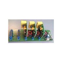
STEVAL-IPE010V1 STMicroelectronics, STEVAL-IPE010V1 Datasheet

STEVAL-IPE010V1
Specifications of STEVAL-IPE010V1
Related parts for STEVAL-IPE010V1
STEVAL-IPE010V1 Summary of contents
Page 1
Features ■ V supply range ■ Two 1 order sigma-delta modulators ■ Programmable chopper-stabilized low noise and low offset amplifier ■ Supports 50- watt meters ■ Internal low-drop regulator at 3 ...
Page 2
Contents Contents 1 Schematic diagram . . . . . . . . . . . . . . . . . . . . . . . . . . . . . . . . . . . ...
Page 3
STPMS1 1 Schematic diagram Figure 1. Block diagram VIP VIP VIN VIN CIP CIP PGA PGA 8x, 32x 8x, 32x CIN CIN VCC VCC LDO LDO GND GND ord ΣΔ ord ΣΔ modulator modulator DIGITAL DIGITAL ...
Page 4
Pin configuration 2 Pin configuration Figure 2. Pin connection (top view) Table 2. Pin description Pin Symbol 1 VDD + 3.0 V output of LDO 2 GND Ground level for signals and pin protection 3 VDDac Current channel modulator supply ...
Page 5
STPMS1 3 Electrical characteristics Table 3. Absolute maximum ratings Symbol VCC DC input voltage I Current on any pin (sink/source) PIN Input voltage at digital pins (MS0, MS1, CLK, DAT DATN) V Input voltage at analog pins (VIP, ...
Page 6
General operating conditions 4 General operating conditions °C, 2.2 µF between 2.048 MHz unless otherwise specified. CLK Table 5. General operating conditions Symbol Parameter General section V Operating ...
Page 7
STPMS1 Table 5. General operating conditions (continued) Symbol Parameter AC measurement accuracy SNR Signal to noise ratio Signal to noise ratio + SINAD distortion THD Total harmonic distortion Spurious free dynamic SFDR range Power supply AC PSRR AC rejection Analog ...
Page 8
General operating conditions Table 5. General operating conditions (continued) Symbol Parameter V Output high voltage OH V Output low voltage OL I Pull up current UP t Transition time TR t Latency L Clock input f Nominal frequencies CLK On ...
Page 9
STPMS1 5 Application The choice of external components in the transduction section of the application is a crucial point in the application design, affecting the precision and the resolution of the whole system. Among the several considerations, a compromise must ...
Page 10
Application Table 6. Suggested external components in metering applications Function Component Calculator Line voltage Resistor interface divider Rogowski coil Line current CT interface Shunt Note: The above listed components refer to typical metering applications. However, STPMS1 operation is not limited ...
Page 11
STPMS1 Figure 6. Connection schematic for DSP based applications Anti Aliasing Anti Aliasing Network Network Anti Aliasing Anti Aliasing Network Network MS0 MS0 MS1 MS1 CIP CIP CLK CLK CIN CIN DAT DAT VIP VIP DATn DATn VIN VIN VCC ...
Page 12
Terminology 6 Terminology 6.1 Conventions The lowest analog and digital power supply voltage is named GND which represents the system Ground. All voltage specifications for digital input/output pins are referred to GND. Positive currents flow into a pin. Sinking current ...
Page 13
STPMS1 7 Typical performance characteristics Figure 7. SNRH of CIP-CIN channel, gain 32x Figure 8. Figure 9. SNHR of VIP-VIN channel Figure 11. SINAD of CIP-CIN channel, gain 8x Figure 12. SINAD of VIP-VIN channel Typical performance characteristics SNHR of ...
Page 14
Typical performance characteristics Figure 13. Relative gain error of CIP-CIN channel, gain 32x Figure 15. Relative gain error of VIP-VIN channel 14/23 Figure 14. Relative gain error of CIP-CIN channel, gain 8x Figure 16. Accuracy over dynamic range Doc ID ...
Page 15
STPMS1 8 Theory of operation 8.1 General operation description The STPMS1 performs first-order analog modulation of signals which have frequencies varying from kHz on two independent channels in parallel. There is a current channel for measuring line ...
Page 16
Theory of operation The band-gap voltage reference is used as the reference level source for the low-drop module and for the AD converters. This module produces several bias currents and voltages for all other analog modules. The low-drop regulator generates ...
Page 17
STPMS1 Figure 18. Block diagram of the modulator 8.3 Functional description of the digital part A digital part is made up of: ● clock generator ● mode decoder ● time multiplex The clock generator produces all five clocks for the ...
Page 18
Package mechanical data 9 Package mechanical data In order to meet environmental requirements, ST offers these devices in different grades of ® ECOPACK packages, depending on their level of environmental compliance. ECOPACK specifications, grade definitions, and product status are available ...
Page 19
STPMS1 Dim. Min 0.18 D 2. 0.30 QFN16 ( mm.) mechanical data mm. Typ. Max. 0.90 1.00 0.05 0.20 0.30 3.00 3.10 1.80 3.00 3.00 ...
Page 20
Package mechanical data Tape & reel QFNxx/DFNxx ( mm.) mechanical data Dim. Min 12 20/23 mm. Typ. Max. Min. 180 13.2 0.504 0.795 2.362 14.4 3.3 ...
Page 21
STPMS1 Figure 19. QFN16 ( mm) footprint recommended data Doc ID 16524 Rev 2 Package mechanical data 21/23 ...
Page 22
Revision history 10 Revision history Table 9. Document revision history Date Revision 23-Oct-2009 1 07-Oct-2010 2 22/23 Initial release. Data brief header removed from the cover page. Doc ID 16524 Rev 2 Changes STPMS1 ...
Page 23
... STPMS1 Information in this document is provided solely in connection with ST products. STMicroelectronics NV and its subsidiaries (“ST”) reserve the right to make changes, corrections, modifications or improvements, to this document, and the products and services described herein at any time, without notice. All ST products are sold pursuant to ST’s terms and conditions of sale. ...


