STEVAL-IPE010V1 STMicroelectronics, STEVAL-IPE010V1 Datasheet - Page 15
STEVAL-IPE010V1
Manufacturer Part Number
STEVAL-IPE010V1
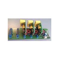
Description
KIT DEMO ENERGY METER STPMC1/S1
Manufacturer
STMicroelectronics
Type
Other Power Managementr
Specifications of STEVAL-IPE010V1
Main Purpose
Power Management, Energy/Power Meter
Embedded
No
Utilized Ic / Part
STPMC1, STPMS1
Maximum Operating Temperature
+ 85 C
Product
Power Management Development Tools
Lead Free Status / RoHS Status
Lead free / RoHS Compliant
Secondary Attributes
-
Primary Attributes
-
Lead Free Status / Rohs Status
Lead free / RoHS Compliant
For Use With/related Products
STPMC1, STPMS1
Other names
497-10754


STPMS1
8
8.1
8.2
Theory of operation
General operation description
The STPMS1 performs first-order analog modulation of signals which have frequencies
varying from DC to 2 kHz on two independent channels in parallel. There is a current
channel for measuring line current and a voltage channel for measuring line voltage. The
outputs of the converters provide two streams of digital ones and zeros which are therefore
multiplexed in time to reduce the number of external connections.
The sampling and the data multiplexing are driven by an external clock signal, as it is used
to strobe the analog inputs. The combination of one or more STPMS1s and an STPMC1
(which implements the digital filtering) constitutes a conversion system for energy metering
applications.
The STPMS1 can also be used along with a DSP programmed to demultiplex the output
bitstream and to implement the digital filtering as a medium resolution ADC system.
When used in energy metering applications, the voltage channel is connected externally and
differentially to a line voltage divider which provides an analog signal proportional to the
voltage u. The current channel is connected to a Rogowski coil, or to a current transformer
(CT) or a shunt, which are used to interface the line current. The Rogowski coil provides an
analog signal proportional to di/dt, while the shunt or CT provides an analog signal
proportional to the current i. A CT differs from a shunt in sensitivity and phase error. There
should be an anti-aliasing LP filter inserted between the sensors and the inputs of both
channels of the STPMS1.
Internally, the differential voltage input related to the voltage channel is connected directly to
the A/D converter, which implies an amplification of x4. On the other side, the differential
voltage input related to the current channel is connected first to a configurable x2 or x8 pre-
amplifier and the output of this pre-amplifier to the similar A/D converter (x4 gain), which
implies selectable pre-amplification of x8 or x32 and uses the same reference voltage.
A pair of digital inputs (MS0 and MS1) is used to configure the device.
Function description of the analog part
The supply pins for the analog part are V
The GND pin also represents a reference point. The V
+3.0 V low-drop voltage regulator, the V
while the V
between V
band-gap, and bias generators.
The analog part consists of several modules:
●
●
●
●
●
Band-gap reference and bias generators
+3 V low-drop regulator
two DC buffer amplifiers
two ΣΔ AD converters
control signal module
DDxx
DDd
is the digital front-end supply input. A 100 nF capacitor should be connected
and GND. The input of the mentioned regulator is V
Doc ID 16524 Rev 2
DDac
CC
, V
and V
DD
, V
CCav
DDac
DD
, V
are the modulators supply inputs,
is an analog I/O pin of an internal
DDav
, V
DDd
CC
, and GND.
Theory of operation
which powers also a
15/23
Related parts for STEVAL-IPE010V1
Image
Part Number
Description
Manufacturer
Datasheet
Request
R

Part Number:
Description:
BOARD DEMO TFT DISPLAY STR91
Manufacturer:
STMicroelectronics
Datasheet:

Part Number:
Description:
BOARD EVAL FOR MEMS SENSORS
Manufacturer:
STMicroelectronics
Datasheet:

Part Number:
Description:
KIT DEV STARTER ST10F276Z5
Manufacturer:
STMicroelectronics
Datasheet:

Part Number:
Description:
BOARD EVAL HDMI $ VIDEO SWITCH
Manufacturer:
STMicroelectronics
Datasheet:

Part Number:
Description:
BOARD DEMO ACCELEROMETER DIL24
Manufacturer:
STMicroelectronics
Datasheet:

Part Number:
Description:
BOARD STLM75/STDS75/ST72F651
Manufacturer:
STMicroelectronics
Datasheet:

Part Number:
Description:
EVAL BOARD 3AXIS MEMS ACCELLRMTR
Manufacturer:
STMicroelectronics
Datasheet:

Part Number:
Description:
BOARD EVAL 8BIT MICRO + TDE1708
Manufacturer:
STMicroelectronics
Datasheet:

Part Number:
Description:
EVAL BOARD A/D TS4657
Manufacturer:
STMicroelectronics
Datasheet:

Part Number:
Description:
BOARD ADAPTER 20DIP LIS3LV02DL
Manufacturer:
STMicroelectronics
Datasheet:
Part Number:
Description:
STMicroelectronics [RIPPLE-CARRY BINARY COUNTER/DIVIDERS]
Manufacturer:
STMicroelectronics
Datasheet:
Part Number:
Description:
STMicroelectronics [LIQUID-CRYSTAL DISPLAY DRIVERS]
Manufacturer:
STMicroelectronics
Datasheet:
Part Number:
Description:
BOARD EVAL FOR MEMS SENSORS
Manufacturer:
STMicroelectronics
Datasheet: