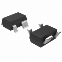
MGA-72543-TR1G Avago Technologies US Inc., MGA-72543-TR1G Datasheet - Page 14

MGA-72543-TR1G
Manufacturer Part Number
MGA-72543-TR1G
Description
IC AMP MMIC LNA GAAS 3V SOT-343
Manufacturer
Avago Technologies US Inc.
Type
General Purpose Amplifierr
Datasheet
1.MGA-72543-TR1G.pdf
(21 pages)
Specifications of MGA-72543-TR1G
Noise Figure
1.42dB
Package / Case
SC-70-4, SC-82-4, SOT-323-4, SOT-343
Current - Supply
60mA ~ 70mA
Frequency
100MHz ~ 6GHz
Gain
13.6dB
P1db
3.2dBm ~ 17.1dBm @ 5mA ~ 60mA
Rf Type
CDMA, TDMA
Test Frequency
2GHz
Voltage - Supply
2.7V ~ 4.2V
Mounting Style
SMD/SMT
Technology
Low Noise Amplifier
Number Of Channels
1
Operating Frequency
6000 MHz
Operating Supply Voltage
3 V
Supply Current
60 mA
Maximum Power Dissipation
250 mW
Maximum Operating Temperature
+ 150 C
Manufacturer's Type
Low Noise Amplifier
Frequency (max)
6GHz
Operating Supply Voltage (min)
2.7V
Operating Supply Voltage (typ)
3V
Operating Supply Voltage (max)
4.2V
Package Type
SOT-343
Mounting
Surface Mount
Pin Count
3 +Tab
Noise Figure (typ)
1.7@6000MHzdB
Lead Free Status / RoHS Status
Lead free / RoHS Compliant
Lead Free Status / RoHS Status
Lead free / RoHS Compliant, Lead free / RoHS Compliant
Other names
516-1829-2
MGA-72543-TR1G
MGA-72543-TR1G
Available stocks
Company
Part Number
Manufacturer
Quantity
Price
Company:
Part Number:
MGA-72543-TR1G
Manufacturer:
AVAGO
Quantity:
201
Company:
Part Number:
MGA-72543-TR1G
Manufacturer:
AVAGO
Quantity:
55 000
Part Number:
MGA-72543-TR1G
Manufacturer:
AVAGO/安华高
Quantity:
20 000
• Gate Bias
Using this method, Pins 1 and 4 of the amplifier are DC
grounded and a negative bias voltage is applied to Pin 3
as shown in Figure 2. This method has the advantage of
not only DC, but also RF grounding both of the ground
pins of the MGA-72543. Direct RF grounding of the
device’s ground pins results in slightly improved perfor-
mance while decreasing potential instabilities, especially
at higher frequencies. The disadvantage is that a negative
supply voltage is required.
Figure 2. Gate Bias Method.
DC access to the input terminal for applying the gate bias
voltage can be made through either a RFC or high imped-
ance transmission line as indicated in Figure 2.
The device current, Id, is determined by the voltage at
Vref (Pin 3) with respect to ground. A plot of typical Id vs.
Vref is shown in Figure 3. Maximum device current (ap-
proximately 65 mA) occurs at Vref = 0.
Figure 3. Device Current vs. Vref.
The device current may also be estimated from the fol-
lowing equation:
Vref = 0.11
where Id is in mA and Vref is in volts.
The gate bias method would not normally be used unless
a negative supply voltage was readily available. For refer-
ence, this is the method used in the characterization test
circuits shown in Figures 1 and 2 of the MGA-72543 data
sheet.
14
INPUT
50
40
30
20
10
-0.80 -0.70 -0.60 -0.50 -0.40
0
V
ref
3
—
I
d
1
– 0.96
V
ref
(V)
4
2
-0.30
OUTPUT
& V
d
-0.20
• Source Resistor Bias
The source resistor method is the simplest way of biasing
the MGA -72543 using a single, positive supply voltage.
This method, shown in Figure 4, places the RF Input (Pin
3) at DC ground and requires both of the device grounds
(Pins 1 and 4) to be RF bypassed. Device current, Id, is
determined by the value of the source resistance, Rbias,
between either Pin 1 or Pin 4 of the MGA-72543 and DC
ground. Note: Pins 1 and 4 are connected internally in the
RFIC. Maximum device current (approximately 65 mA)
occurs for Rbias = 0.
Figure 4. Source Resistor Bias.
A simple method recommended for DC grounding the
input terminal is to merely add a resistor from Pin 3 to
ground, as shown in Figure 4. The value of the shunt R can
be comparatively high since the only voltage drop across
it is due to minute leakage currents that in the μA range.
A value of 1 KΩ would adequately DC ground the input
while loading the RF signal by only 0.2 dB loss.
A plot of typical Id vs. Rbias is shown in Figure 5.
Figure 5. Device Current vs. R
The approximate value of the external resistor, Rbias, may
also be calculated from:
where Rbias is in ohms and Id is the desired device current
in mA.
The source resistor technique is the preferred and most
common method of biasing the MGA -72543.
INPUT
Rbias = 964 (1 – 0.112
60
50
40
30
20
10
0
0
20
Id
3
40
1
60
R
R
bias
bias
4
80
2
bias
()
.
—
100
OUTPUT
Id)
& V
d
120
140


