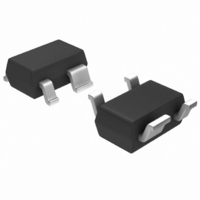
MGA-72543-TR1G Avago Technologies US Inc., MGA-72543-TR1G Datasheet - Page 18

MGA-72543-TR1G
Manufacturer Part Number
MGA-72543-TR1G
Description
IC AMP MMIC LNA GAAS 3V SOT-343
Manufacturer
Avago Technologies US Inc.
Type
General Purpose Amplifierr
Datasheet
1.MGA-72543-TR1G.pdf
(21 pages)
Specifications of MGA-72543-TR1G
Noise Figure
1.42dB
Package / Case
SC-70-4, SC-82-4, SOT-323-4, SOT-343
Current - Supply
60mA ~ 70mA
Frequency
100MHz ~ 6GHz
Gain
13.6dB
P1db
3.2dBm ~ 17.1dBm @ 5mA ~ 60mA
Rf Type
CDMA, TDMA
Test Frequency
2GHz
Voltage - Supply
2.7V ~ 4.2V
Mounting Style
SMD/SMT
Technology
Low Noise Amplifier
Number Of Channels
1
Operating Frequency
6000 MHz
Operating Supply Voltage
3 V
Supply Current
60 mA
Maximum Power Dissipation
250 mW
Maximum Operating Temperature
+ 150 C
Manufacturer's Type
Low Noise Amplifier
Frequency (max)
6GHz
Operating Supply Voltage (min)
2.7V
Operating Supply Voltage (typ)
3V
Operating Supply Voltage (max)
4.2V
Package Type
SOT-343
Mounting
Surface Mount
Pin Count
3 +Tab
Noise Figure (typ)
1.7@6000MHzdB
Lead Free Status / RoHS Status
Lead free / RoHS Compliant
Lead Free Status / RoHS Status
Lead free / RoHS Compliant, Lead free / RoHS Compliant
Other names
516-1829-2
MGA-72543-TR1G
MGA-72543-TR1G
Available stocks
Company
Part Number
Manufacturer
Quantity
Price
Company:
Part Number:
MGA-72543-TR1G
Manufacturer:
AVAGO
Quantity:
201
Company:
Part Number:
MGA-72543-TR1G
Manufacturer:
AVAGO
Quantity:
55 000
Part Number:
MGA-72543-TR1G
Manufacturer:
AVAGO/安华高
Quantity:
20 000
Other currents can be set by positioning the DIP switch
to the bypass state and adding an external bias resistor to
Vcon. Unless an external resistor is used to set the current,
the Vcon terminal is left open. DC blocking capacitors are
provided for the both the input and output.
The 2-pin, 0.100” centerline single row headers attached
to the Vd and Vcon connections on the PCB provide a
convenient means of making connections to the board
using either a mating connector or clip leads.
A Note on Performance
Actual performance of the MGA-72543 as measured in
an evaluation circuit may not exactly match the data
sheet specifications. The circuit board material, passive
components, RF bypasses, and connectors all introduce
losses and parasitics that degrade device performance.
For the evaluation circuit above, fabricated on 0.031-inch
thick GETEK
losses of about 0.3 dB would be expected at both the input
an output sides of the RFIC at 1900 MHz. Measured noise
figure (3 volts, 20 mA bias) would then be approximately
1.8 dB and gain 13.8 dB.
Figure 13. Completed Amplifier with Component Reference Designators.
18
[1]
G200D (Hr = 4.2) dielectric material, circuit
IN
R2 C0
R1
C1
C
C0
C3
SW
L1
R4
ON
1
C5
72
C4
C
2
SC
R3
C8
C
C2
RFC
MGA-71, MGA-72
C0
Out
HM 8/98
Table 1. Component Values for 1900 MHz Amplifier.
Hints and Troubleshooting
• Preventing Oscillation
Stability of the MGA-72543 is dependent on having very
good RF grounding. Inadequate device grounding or
poor PCB layout techniques could cause the device to be
potentially unstable.
[1] General Electric Co.
R1 =
R2 =
R3 =
R4 =
L1 =
RFC =
SW1, SW2
SC
Figure 14. Schematic Diagram of 1900 MHz Evaluation Amplifier.
Input
Vin
RF
R2
5.1 KΩ
5.1 KΩ
10Ω
24Ω
3.9 nH
22 nH
DIP switch
Short
V
d
C1
C3
C0
R1
L1
C
C (3 ea)
C (3 ea)
C1
C2
C3
C4
C5
C6
C0
C4
3
1
72
C5
SW1
SW2
=100 pF
=1000 pF
=100 pF
= 47 pF
= 30 pF
= 22 pF
=22 pF
=30 pF
C
2
4
R
R3
R4
bias
C6
RFC
Vcon
C0
C2
C
Output
RF


