MICRF505DEV1 Micrel Inc, MICRF505DEV1 Datasheet - Page 24
MICRF505DEV1
Manufacturer Part Number
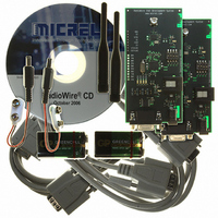
MICRF505DEV1
Description
KIT DEV RADIOWIRE 850-950MHZ
Manufacturer
Micrel Inc
Series
RadioWire®r
Type
Transceiver, ISMr
Specifications of MICRF505DEV1
Frequency
850MHz ~ 950MHz
For Use With/related Products
MICRF505
Lead Free Status / RoHS Status
Lead free / RoHS Compliant
Other names
576-1606
Available stocks
Company
Part Number
Manufacturer
Quantity
Price
Company:

Part Number:
MICRF505DEV1
Manufacturer:
Micrel Inc
Quantity:
135


Transmitter
Power Amplifier
The maximum output power is approximately 10dBm
for a 50 Ω load. For maximum output power the load
seen by the PA must be resistive. Higher output
power can be obtained by decreasing the load
impedance. However, this will be in conflict with
obtaining impedance match in the LNA. The output
power is programmable in seven steps, with
approximately 3dB between each step. This is
controlled by bits PA2 – PA0.
The power amplifier can be turned off by setting PA2
– PA0 = 0.
For all other combinations the PA is on and has
maximum power when PA2 – PA0 = 1.
The PA will be bypassed if PA_by=1. Output power
will drop ~15dB. It is still possible to control the
power by PA2 – PA0.
The output power varies about 3dB over power
supply 2.0V to 2.5V and about 2dB over temperature
-40˚C to +85˚C. The 2
are as follows:
2
3
To reduce the emission of harmonics, an LC filter
can be added between the ANT pin and the antenna
as shown in Figure 15.
This filter is designed for the 915MHz band with 50Ω
terminations. The component values may have to be
tuned to compensate for the layout parasitics. This
filter may also increase the receiver selectivity.
nd
rd
October 2006
harmonic:
harmonic:
0000000
0000001
0000010
A6..A0
50ohm line
C6
2p2
<-20dBm
<-26dBm
Figure 15. LC Filter
Modulation1
L1
8n7
LNA_by
CP_HI
D7
nd
and 3
C5
8p2
rd
Modulation0
harmonic of the PA
50ohm line
SC_by
C4
3p3
PA2
D6
ANT
PA1
D5
‘0’
‘0’
24
PA_By
PA0
D4
‘0’
0000001
A6..A0
Frequency Modulation
Modulation1
When Modulation1 and Modulation0 is 00, the
modulator needs to be programmed properly, see
“Modulator” section. The modulation signal will now
be applied directly on the phase locked VCO. It is
therefore important that the PLL bandwidth is not too
high, as this will remove the modulation. See “PLL
Filter” section on how to calculate the PLL
components.
modulation signal is applied to the VCO and
therefore some sort of encoding is needed.
The level of encoding is determined by the PLL loop
filter bandwidth and data rate. Two of the most
common encoding techniques are Manchester
encoding and 3B4B. Other encoding schemes may
also be used.
Manchester encoding is when one bit is encoded in
to a two-bit word and is shown in Table 10. When
using Manchester encoding the maximum overhead
is 100%. When selecting PLL loop filter it is
important to note that the min baud rate is equal to:
0
0
1
1
Modulation1
RSSI_en
Sync_en
f
rate [Hz]
baud/s: Elements per second (encoded data)
OUTS3
baud_min
f
baud_min
D7
D3
Table 11. Modulation Bit Setting
Table 12. Manchester Encoding
: The minimum frequency of the baud
Data
Modulation0
=
Modulation0
“0”
“1”
When
D6
baud /s
OUTS2
Mode1
LD_en
0
1
0
1
D2
4
D5
‘0’
using
D4
‘0’
PF_FC1
OUTS1
Modulation Type
Closed loop modulation
using modulator
Not in use
FSK applied using two
sets of dividers
Not in use
Mode0
RSSI_en
D1
the
D3
+1 408-944-0800
modulator
LD_en
M9999-103106
D2
Word
“10”
“01”
Load_en
PF_FC0
OUTS0
PF_FC1
D0
D1
the
PF_FC0
D0
Related parts for MICRF505DEV1
Image
Part Number
Description
Manufacturer
Datasheet
Request
R

Part Number:
Description:
Manufacturer:
Micrel Inc
Datasheet:
Part Number:
Description:
Manufacturer:
Micrel Inc
Datasheet:
Part Number:
Description:
Manufacturer:
Micrel Inc
Datasheet:
Part Number:
Description:
Manufacturer:
Micrel Inc
Datasheet:
Part Number:
Description:
Manufacturer:
Micrel Inc
Datasheet:
Part Number:
Description:
Manufacturer:
Micrel Inc
Datasheet:
Part Number:
Description:
Manufacturer:
Micrel Inc
Datasheet:
Part Number:
Description:
Manufacturer:
Micrel Inc
Datasheet:
Part Number:
Description:
Manufacturer:
Micrel Inc
Datasheet:
Part Number:
Description:
Manufacturer:
Micrel Inc
Datasheet:
Part Number:
Description:
Manufacturer:
Micrel Inc
Datasheet:
Part Number:
Description:
Manufacturer:
Micrel Inc
Datasheet:
Part Number:
Description:
Manufacturer:
Micrel Inc
Datasheet:
Part Number:
Description:
Manufacturer:
Micrel Inc
Datasheet: