MICRF505DEV1 Micrel Inc, MICRF505DEV1 Datasheet - Page 27
MICRF505DEV1
Manufacturer Part Number
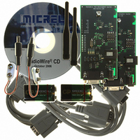
MICRF505DEV1
Description
KIT DEV RADIOWIRE 850-950MHZ
Manufacturer
Micrel Inc
Series
RadioWire®r
Type
Transceiver, ISMr
Specifications of MICRF505DEV1
Frequency
850MHz ~ 950MHz
For Use With/related Products
MICRF505
Lead Free Status / RoHS Status
Lead free / RoHS Compliant
Other names
576-1606
Available stocks
Company
Part Number
Manufacturer
Quantity
Price
Company:

Part Number:
MICRF505DEV1
Manufacturer:
Micrel Inc
Quantity:
135


Modulator Attenuator
A third way to set the deviation is by programming
the modulator attenuator, Mod_A2..Mod_A0, the last
being LSB. The purpose of the attenuator is to allow
small deviations when the bit rate is small and/or the
BT is small (these settings will give a relatively slow
modulator clock, and therefore long rise- and fall
times, which in turn results in large frequency
deviations). In addition, the attenuator will improve
the resolution of the modulator.
The effect of the attenuator is given by:
Figure 22 shows two waveforms with different
attenuator setting:
increased, the frequency deviation is lowered and
vice versa.
Modulator Filter
To reduce the high-frequency components in the
generated waveform, a filter with programmable cut-
off frequency can be enabled. This is done using
Mod_F2..Mod_F0, the least one being LSB. The
Mod_F should be set according to the formula:
October 2006
Figure 21. Two Different Modulator Current Settings
Figure 22. Two Different Modulator Attenuator
Mod_Ab > Mod_Ab
Mod_la > Mod_lb
Mod_la
Mod_lb
Mod_Aa
Mod_Ab
f
DEVIATION
MOD F
Mod Aa
_
Settings
_
∝
=
1
150 10
<
+
BitRate
Mod Ab
Mod_A
×
1
_
3
. If Mod_A is
27
Mod_F=0 disables the modulator filter and Mod_F=7
gives most filtering. Figure 23 shows a waveform
with and without the filter.
Calculation of the Frequency Deviation
The parameters influencing the frequency deviation
can be summarized in the following equations:
Where:
Figure 23. Modulator Waveform with and without
f
f
f
f
Refclk_K:
Mod_clkS:
f
Mod_I:
Mod_A:
C1:
C2:
DEV
DEV
XCO
RF
MOD_CLK
:
:
:
f
=
Mod_filter off
MOD_CLK
f
MOD_CLK
:
Mod_I
=
Single sided frequency deviation
[Hz].
Crystal oscillator frequency [Hz].
Center frequency [Hz].
6 bit divider, values between 1
and 63.
Modulator clock setting, values
between 0 and 7.
Modulator
derived
frequency,
Mod_clkS.
Modulator
values between 0 and 31.
Modulator
values between 0 and 15.
72
−
Refclk_K 2
⋅
4.42 10
Filtering
Mod_filter on
1 Mod_A
+
×
1
10
f
XCO
⋅
from
(7-Mod_clkS)
attenuator
⋅
clock
(
current
C
Refclk_K
+1 408-944-0800
1
+
M9999-103106
C f
the
2
⋅
frequency,
RF
setting,
setting,
)
crystal
and
Related parts for MICRF505DEV1
Image
Part Number
Description
Manufacturer
Datasheet
Request
R

Part Number:
Description:
Manufacturer:
Micrel Inc
Datasheet:
Part Number:
Description:
Manufacturer:
Micrel Inc
Datasheet:
Part Number:
Description:
Manufacturer:
Micrel Inc
Datasheet:
Part Number:
Description:
Manufacturer:
Micrel Inc
Datasheet:
Part Number:
Description:
Manufacturer:
Micrel Inc
Datasheet:
Part Number:
Description:
Manufacturer:
Micrel Inc
Datasheet:
Part Number:
Description:
Manufacturer:
Micrel Inc
Datasheet:
Part Number:
Description:
Manufacturer:
Micrel Inc
Datasheet:
Part Number:
Description:
Manufacturer:
Micrel Inc
Datasheet:
Part Number:
Description:
Manufacturer:
Micrel Inc
Datasheet:
Part Number:
Description:
Manufacturer:
Micrel Inc
Datasheet:
Part Number:
Description:
Manufacturer:
Micrel Inc
Datasheet:
Part Number:
Description:
Manufacturer:
Micrel Inc
Datasheet:
Part Number:
Description:
Manufacturer:
Micrel Inc
Datasheet: