1320X-QE-DSK-BDM Freescale Semiconductor, 1320X-QE-DSK-BDM Datasheet - Page 18
1320X-QE-DSK-BDM
Manufacturer Part Number
1320X-QE-DSK-BDM
Description
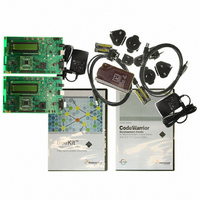
KIT EVAL FOR MC1320X BDM CABLE
Manufacturer
Freescale Semiconductor
Type
Transceiver, 802.15.4/ZigBeer
Specifications of 1320X-QE-DSK-BDM
Frequency
2.4GHz
Interface Type
USB
For Use With/related Products
MC1320x
Lead Free Status / RoHS Status
Lead free / RoHS Compliant


System Overview and Functional Block Descriptions
3.5
The module provides multiple interfaces for both debug and demonstration.
3.5.1
Primary communication with an application device or platform is provided by a USB port with a USB “B”
receptacle plug. USB connectivity is provided by a FTDI FT232R USB < > UART device that appears as
a virtual COM port (VCP) to a connected PC. PC drivers are provided with the module. For pinout
information, see
The USB interface is configured as a “bus powered” device and can draw all required power from the USB
interface. The device is USB 2.0 full speed compatible.
3.5.2
The 1320x-QE128EVB supports a 16x2 monochrome character LCD that provides for alpha-numeric
readout. The LCD module is mounted on top of the main circuit board and connects via a 16 pin header
with 0.1in spacing. For pinout information, see
3-6
PTC2/RXTXEN
PTB2/SPSCK 1
PTC3/GPIO1
PTC4/GPIO2
PTB4/MISO 1
PTB3/MOSI 1
PTC1/ATTN
PTC0/RST
PTB5/SS1
•
•
•
•
•
•
CLKO
IRQ
USB 2.0 full speed compatible interface
16 x 2 monochrome character LCD display
BDM Debug and Development interface
Four individual pushbuttons can be used as input and have interrupt generation capability
Four individual LEDs can be used as indicators for debug or status
A fully buffered RS232 serial interface with RTS/CTS control is supplied as a secondary COM port
Interfaces
USB Interface
16x2 Monochrome Character LCD Display
C9
C9
8PF
8PF
Section 4.5, “USB Connector (“B”
1
2
NX3225SA-16.000000MHZ
NX3225SA-16.000000MHZ
Y1
Y1
4
3
C10
C10
8PF
8PF
TP11
TP11
TP10
TP10
TP9
TP9
TP8
TP8
TP7
TP7
1320x-QE128EVB Reference Manual, Rev. 1.0
Figure 3-4. RF Interface Network
11
10
23
24
25
19
18
17
16
20
14
13
12
15
26
27
33
9
8
7
U1
U1
MC13202FC
MC13202FC
GPIO1
GPIO2
GPIO3
GPIO4
GPIO5
GPIO6
GPIO7
/CE
MISO
MOSI
SPICLK
/IRQ
/ATTN
RXTXEN
/RST
CLKO
XTAL1
XTAL2
SM
EP
R1
R1
10K
10K
VDDVCO
VDDLO1
VDDLO2
CT_Bias
VDDINT
PAO_M
VBATT
PAO_P
RIN_M
VDDD
RIN_P
VDDA
NC
Section 4.6, “LCD
31
22
32
29
28
21
30
2
1
3
5
6
4
R46
R46
470K
470K
Receptacle)”.
C1
C1
0.1UF
0.1UF
1
1
J1 and R20 for
Current and
Voltage
Measurements
L1
L1
1.8nH
1.8nH
L3
L3
1.8nH
1.8nH
DNP
DNP
C3
C3
0.1UF
0.1UF
R20
R20
0 OHM
0 OHM
2
2
C4
C4
0.1UF
0.1UF
L2
L2
3.9nH
3.9nH
Connector”.
2
1
HDR_2X1
HDR_2X1
C2
C2
0.1UF
0.1UF
C8
C8
10PF
10PF
V_RF
J1
J1
3
2
4
LDB212G4005C-001
LDB212G4005C-001
V_RF
Z1
Z1
1
5
6
C5
C5
10PF
10PF
DNP
DNP
C6
C6
10PF
10PF
Freescale Semiconductor
142-0701-801
142-0701-801
CN1
CN1
SMA
SMA
DNP
DNP
C7
C7
1PF
1PF
DNP
DNP
L4
L4
3.9nH
3.9nH
DNP
DNP
ANT1
ANT1
F_Antenna
F_Antenna
Related parts for 1320X-QE-DSK-BDM
Image
Part Number
Description
Manufacturer
Datasheet
Request
R

Part Number:
Description:
KIT DEV FOR MC1320X QE RFIC
Manufacturer:
Freescale Semiconductor
Datasheet:

Part Number:
Description:
Manufacturer:
Freescale Semiconductor, Inc
Datasheet:
Part Number:
Description:
Manufacturer:
Freescale Semiconductor, Inc
Datasheet:
Part Number:
Description:
Manufacturer:
Freescale Semiconductor, Inc
Datasheet:
Part Number:
Description:
Manufacturer:
Freescale Semiconductor, Inc
Datasheet:
Part Number:
Description:
Manufacturer:
Freescale Semiconductor, Inc
Datasheet:
Part Number:
Description:
Manufacturer:
Freescale Semiconductor, Inc
Datasheet:
Part Number:
Description:
Manufacturer:
Freescale Semiconductor, Inc
Datasheet:
Part Number:
Description:
Manufacturer:
Freescale Semiconductor, Inc
Datasheet:
Part Number:
Description:
Manufacturer:
Freescale Semiconductor, Inc
Datasheet:
Part Number:
Description:
Manufacturer:
Freescale Semiconductor, Inc
Datasheet:
Part Number:
Description:
Manufacturer:
Freescale Semiconductor, Inc
Datasheet:
Part Number:
Description:
Manufacturer:
Freescale Semiconductor, Inc
Datasheet:
Part Number:
Description:
Manufacturer:
Freescale Semiconductor, Inc
Datasheet:
Part Number:
Description:
Manufacturer:
Freescale Semiconductor, Inc
Datasheet: