1320X-QE-DSK-BDM Freescale Semiconductor, 1320X-QE-DSK-BDM Datasheet - Page 22
1320X-QE-DSK-BDM
Manufacturer Part Number
1320X-QE-DSK-BDM
Description
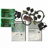
KIT EVAL FOR MC1320X BDM CABLE
Manufacturer
Freescale Semiconductor
Type
Transceiver, 802.15.4/ZigBeer
Specifications of 1320X-QE-DSK-BDM
Frequency
2.4GHz
Interface Type
USB
For Use With/related Products
MC1320x
Lead Free Status / RoHS Status
Lead free / RoHS Compliant


Interface Locations and Pinouts
4.2
The module can be powered from the DC power jack, the USB port, or the battery pack.
4.2.1
Table 4-1
mA.
4.2.2
The slide switch designated SW1 provides an on/off function and the only hardware reset to the main board
and subsystems.
4.2.3
Green light emitting diode LED5 is the power on indicator for any source. The LED is active anytime a
power source is present and SW1 is ON. If the power source is the USB connection, LED5 will be inactive
when SW1 is open (off), but the USB interface device will be powered as long as connected to the USB
bus.
4-2
AA Battery Pack BT1
DC Source
•
•
Source
USB
The hardware reset was implemented through power on/off because of the IO/reset configuration
of the MC9S08QE128 MCU. The MCU has a single pin that can be used as an external interrupt
request (IRQ) or hardware reset input. In this application the MC1320x transceiver requires use of
the external IRQ function, and as a result, the MCU cannot directly use the hardware reset pin. For
the module, the only hardware reset is to cycle main power through SW1.
When the module is powered from the USB connection, the USB interface IC is always powered
and SW1 does not disconnect power from it. This has been done such that switching power via
SW1 does not disrupt connection with a PC and cause software driver problems with the
applications software.
Power Management
lists the supply sources, connectors, and voltages. Maximum board current draw is rated at 100
Supply Sources
On/Off Switch (Hardware Reset)
Power On Indicator
J12
J2
Connector
(Volts)
~2.0
Min
4.4
4.4
1320x-QE128EVB Reference Manual, Rev. 1.0
Table 4-1. Power Supply Sources
Typical
(Volts)
5
5
3
(Volts)
Max
5.25
3.2
12
Use DC only source. The connector is a 2 mm DC power jack;
positive center conductor.
Per USB specification. Power from USB connector.
Two AA cells. Battery pack is automatically disabled by either
DC source or USB.
Notes
Freescale Semiconductor
Related parts for 1320X-QE-DSK-BDM
Image
Part Number
Description
Manufacturer
Datasheet
Request
R

Part Number:
Description:
KIT DEV FOR MC1320X QE RFIC
Manufacturer:
Freescale Semiconductor
Datasheet:

Part Number:
Description:
Manufacturer:
Freescale Semiconductor, Inc
Datasheet:
Part Number:
Description:
Manufacturer:
Freescale Semiconductor, Inc
Datasheet:
Part Number:
Description:
Manufacturer:
Freescale Semiconductor, Inc
Datasheet:
Part Number:
Description:
Manufacturer:
Freescale Semiconductor, Inc
Datasheet:
Part Number:
Description:
Manufacturer:
Freescale Semiconductor, Inc
Datasheet:
Part Number:
Description:
Manufacturer:
Freescale Semiconductor, Inc
Datasheet:
Part Number:
Description:
Manufacturer:
Freescale Semiconductor, Inc
Datasheet:
Part Number:
Description:
Manufacturer:
Freescale Semiconductor, Inc
Datasheet:
Part Number:
Description:
Manufacturer:
Freescale Semiconductor, Inc
Datasheet:
Part Number:
Description:
Manufacturer:
Freescale Semiconductor, Inc
Datasheet:
Part Number:
Description:
Manufacturer:
Freescale Semiconductor, Inc
Datasheet:
Part Number:
Description:
Manufacturer:
Freescale Semiconductor, Inc
Datasheet:
Part Number:
Description:
Manufacturer:
Freescale Semiconductor, Inc
Datasheet:
Part Number:
Description:
Manufacturer:
Freescale Semiconductor, Inc
Datasheet: