1320X-QE-DSK-BDM Freescale Semiconductor, 1320X-QE-DSK-BDM Datasheet - Page 20
1320X-QE-DSK-BDM
Manufacturer Part Number
1320X-QE-DSK-BDM
Description
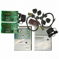
KIT EVAL FOR MC1320X BDM CABLE
Manufacturer
Freescale Semiconductor
Type
Transceiver, 802.15.4/ZigBeer
Specifications of 1320X-QE-DSK-BDM
Frequency
2.4GHz
Interface Type
USB
For Use With/related Products
MC1320x
Lead Free Status / RoHS Status
Lead free / RoHS Compliant


System Overview and Functional Block Descriptions
3.7
The primary clock source for the 1320x-QE128EVB is supplied by the MC1320x transceiver. The
transceiver requires an accurate 16 MHz reference clock that is supplied via an on-board 16 MHz crystal
oscillator, and in turn, the transceiver typically supplies the clock for the MCU. However, there are options
for the MCU clock usage:
The external source of clock is selected by Jumper (J5) (See
3-8
•
•
•
The default clock source for the QE128 is obtained through MC1320x CLKO programmable
frequency clock output. The RF transceiver reference oscillator is 16 MHz and the mounted crystal
Y1 is a 16 MHz device that meets MC1320x specifications. In turn, CLKO can be enabled to
provide the clock source to the MCU as an external input.
The QE128 Internal Clock Source (ICS) supplies an optional on-board reference oscillator (32KHz
nominal). With use of the on-board Frequency-locked-loop (FLL), CPU frequencies from 2-50
MHz are available. Precision trimming of the internal reference allows for 0.2% resolution and 2%
deviation over temperature and voltage.
The module also supports optional use of an external 32.768KHz crystal for the MCU. The
on-board MCU clock amp is used with the 32KHz crystal, and higher CPU and bus clock
frequencies are again synthesized through use of the on-board FLL in the ICS.
Clocks
1320x-QE128EVB Reference Manual, Rev. 1.0
Section 4.11, “Jumper
Selection”).
Freescale Semiconductor
Related parts for 1320X-QE-DSK-BDM
Image
Part Number
Description
Manufacturer
Datasheet
Request
R

Part Number:
Description:
KIT DEV FOR MC1320X QE RFIC
Manufacturer:
Freescale Semiconductor
Datasheet:

Part Number:
Description:
Manufacturer:
Freescale Semiconductor, Inc
Datasheet:
Part Number:
Description:
Manufacturer:
Freescale Semiconductor, Inc
Datasheet:
Part Number:
Description:
Manufacturer:
Freescale Semiconductor, Inc
Datasheet:
Part Number:
Description:
Manufacturer:
Freescale Semiconductor, Inc
Datasheet:
Part Number:
Description:
Manufacturer:
Freescale Semiconductor, Inc
Datasheet:
Part Number:
Description:
Manufacturer:
Freescale Semiconductor, Inc
Datasheet:
Part Number:
Description:
Manufacturer:
Freescale Semiconductor, Inc
Datasheet:
Part Number:
Description:
Manufacturer:
Freescale Semiconductor, Inc
Datasheet:
Part Number:
Description:
Manufacturer:
Freescale Semiconductor, Inc
Datasheet:
Part Number:
Description:
Manufacturer:
Freescale Semiconductor, Inc
Datasheet:
Part Number:
Description:
Manufacturer:
Freescale Semiconductor, Inc
Datasheet:
Part Number:
Description:
Manufacturer:
Freescale Semiconductor, Inc
Datasheet:
Part Number:
Description:
Manufacturer:
Freescale Semiconductor, Inc
Datasheet:
Part Number:
Description:
Manufacturer:
Freescale Semiconductor, Inc
Datasheet: