ATAKSTK511-8 Atmel, ATAKSTK511-8 Datasheet - Page 12
ATAKSTK511-8
Manufacturer Part Number
ATAKSTK511-8
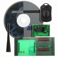
Description
KIT RF MODULE 868MHZ FOR STK500
Manufacturer
Atmel
Series
SmartRF®r
Type
Transmitter, Receiver, ASK, FSKr
Specifications of ATAKSTK511-8
Frequency
868MHz
Wireless Frequency
868 MHz
For Use With/related Products
ATSTK500
Lead Free Status / RoHS Status
Contains lead / RoHS non-compliant


1925C–AVR–3/03
Hardware Description
3.2
3-2
Description of
User Switches
Figure 3-2. Implementation of LEDs and LED Headers
Note:
The switches connected to the debug headers are implemented as shown in Figure 3-3.
Pushing a switch causes the corresponding SWx to be pulled low, while releasing it will
result in VTG on the appropriate switch header connector. Valid target voltage range is
1.8V < VTG < 6.0V.
Figure 3-3. Implementation of Switches and Switch Headers
Note:
The AVR can source or sink enough current to drive a LED directly. In the
STK500 design, a transistor with two resistors is used to give the same amount
of light from the LED, whatever the target voltage (VTG) may be and to turn off
the LEDs when VTG is missing.
In the AVR, the user can enable internal pull-ups on the input pins, removing the
need for an external pull-up on the push-button. In the STK500 design, we have
added an external 10K pull-up to give all users a logical “1” on SWn when the
push-button is not pressed. The 150R resistor limits the current going into the
AVR.
SW n
VTG
LEDn
10K
150R
+5V
150R
VTG
10K
SW n
LED0
LED2
LED4
LED6
GND
GND
SW0
SW2
SW4
SW6
1 2
1 2
LED1
LED3
LED5
LED7
VTG
SW1
SW3
SW5
SW7
VTG
AVR STK500 User Guide
Related parts for ATAKSTK511-8
Image
Part Number
Description
Manufacturer
Datasheet
Request
R

Part Number:
Description:
DEV KIT FOR AVR/AVR32
Manufacturer:
Atmel
Datasheet:

Part Number:
Description:
INTERVAL AND WIPE/WASH WIPER CONTROL IC WITH DELAY
Manufacturer:
ATMEL Corporation
Datasheet:
Part Number:
Description:
Low-Voltage Voice-Switched IC for Hands-Free Operation
Manufacturer:
ATMEL Corporation
Datasheet:
Part Number:
Description:
MONOLITHIC INTEGRATED FEATUREPHONE CIRCUIT
Manufacturer:
ATMEL Corporation
Datasheet:
Part Number:
Description:
AM-FM Receiver IC U4255BM-M
Manufacturer:
ATMEL Corporation
Datasheet:
Part Number:
Description:
Monolithic Integrated Feature Phone Circuit
Manufacturer:
ATMEL Corporation
Datasheet:
Part Number:
Description:
Multistandard Video-IF and Quasi Parallel Sound Processing
Manufacturer:
ATMEL Corporation
Datasheet:
Part Number:
Description:
High-performance EE PLD
Manufacturer:
ATMEL Corporation
Datasheet:
Part Number:
Description:
8-bit Flash Microcontroller
Manufacturer:
ATMEL Corporation
Datasheet:
Part Number:
Description:
2-Wire Serial EEPROM
Manufacturer:
ATMEL Corporation
Datasheet: