ATAKSTK511-8 Atmel, ATAKSTK511-8 Datasheet - Page 23
ATAKSTK511-8
Manufacturer Part Number
ATAKSTK511-8
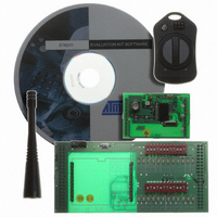
Description
KIT RF MODULE 868MHZ FOR STK500
Manufacturer
Atmel
Series
SmartRF®r
Type
Transmitter, Receiver, ASK, FSKr
Specifications of ATAKSTK511-8
Frequency
868MHz
Wireless Frequency
868 MHz
For Use With/related Products
ATSTK500
Lead Free Status / RoHS Status
Contains lead / RoHS non-compliant


AVR STK500 User Guide
Jumpers
must be
Mounted
Figure 3-18. Jumper Settings for High-voltage Programming
Device-
dependent
Jumpers
(See Below)
Hardware setup for parallel High-voltage Programming:
1. Switch power off.
2. Place the device to program in its socket according to Table 3-3 on page 3-11.
3. Connect the headers PROGDATA and PORTB with the 10-wire cable.
4. Connect the headers PROGCTRL and PORTD with the 10-wire cable.
5. Mount jumper OSCSEL on pins 1 and 2 to select software-controlled clock.
6. Mount jumper XTAL1 to route the oscillator signal to the device.
7. Mount jumpers VTARGET and RESET.
8. When programming AT90S2333, AT90S4433, or ATmega8, mount both PJUMP
9. When programming ATmega16, ATmega163, ATmega161, ATmega128, or
10. Disconnect target system.
11. Switch power on.
12. Ensure that VTARGET is between 4.5V and 5.5V before programming. See Sec-
For a complete description of jumper settings, see Section 3.8, “Jumper Settings”.
Note:
jumpers. The 2-wire cables can be used instead of jumpers.
ATmega323, mount the BSEL2 jumper. When programming ATmega8, connect
BSEL2 terminal to PC2. A 2-wire cable can be used instead of jumpers.
tion 5.3.5.1.
Remove the hardware setup for High-voltage Programming before starting a
debug session.
VTARGET
OSCSEL
PJUMP
RESET
BSEL2
XTAL1
AREF
Hardware Description
1925C–AVR–3/03
3-13
Related parts for ATAKSTK511-8
Image
Part Number
Description
Manufacturer
Datasheet
Request
R

Part Number:
Description:
DEV KIT FOR AVR/AVR32
Manufacturer:
Atmel
Datasheet:

Part Number:
Description:
INTERVAL AND WIPE/WASH WIPER CONTROL IC WITH DELAY
Manufacturer:
ATMEL Corporation
Datasheet:
Part Number:
Description:
Low-Voltage Voice-Switched IC for Hands-Free Operation
Manufacturer:
ATMEL Corporation
Datasheet:
Part Number:
Description:
MONOLITHIC INTEGRATED FEATUREPHONE CIRCUIT
Manufacturer:
ATMEL Corporation
Datasheet:
Part Number:
Description:
AM-FM Receiver IC U4255BM-M
Manufacturer:
ATMEL Corporation
Datasheet:
Part Number:
Description:
Monolithic Integrated Feature Phone Circuit
Manufacturer:
ATMEL Corporation
Datasheet:
Part Number:
Description:
Multistandard Video-IF and Quasi Parallel Sound Processing
Manufacturer:
ATMEL Corporation
Datasheet:
Part Number:
Description:
High-performance EE PLD
Manufacturer:
ATMEL Corporation
Datasheet:
Part Number:
Description:
8-bit Flash Microcontroller
Manufacturer:
ATMEL Corporation
Datasheet:
Part Number:
Description:
2-Wire Serial EEPROM
Manufacturer:
ATMEL Corporation
Datasheet: