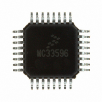
MC33596FJER2 Freescale Semiconductor, MC33596FJER2 Datasheet - Page 13

MC33596FJER2
Manufacturer Part Number
MC33596FJER2
Description
IC RX UHF PLL TUNED 32-LQFP
Manufacturer
Freescale Semiconductor
Datasheet
1.MC33596FCAE.pdf
(70 pages)
Specifications of MC33596FJER2
Frequency
304, 315, 426, 434, 868 & 915MHz
Sensitivity
-104dBm
Data Rate - Maximum
22.4 kBaud
Modulation Or Protocol
FSK, OOK
Applications
General Data Transfer
Current - Receiving
10.3mA
Data Interface
PCB, Surface Mount
Antenna Connector
PCB, Surface Mount
Voltage - Supply
2.7 V ~ 3.6 V, 4.5 V ~ 5.5 V
Operating Temperature
-40°C ~ 85°C
Package / Case
32-LQFP
Operating Temperature (min)
-40C
Operating Temperature (max)
85C
Operating Temperature Classification
Industrial
Modulation Type
FSK/OOK
Package Type
LQFP
Operating Supply Voltage (min)
2.7V
Lead Free Status / RoHS Status
Lead free / RoHS Compliant
Features
-
Memory Size
-
Lead Free Status / Rohs Status
Compliant
Available stocks
Company
Part Number
Manufacturer
Quantity
Price
Part Number:
MC33596FJER2
Manufacturer:
FREESCALE
Quantity:
20 000
11.1.2 Data Manager Disabled and Strobe Oscillator Enabled
Raw received data is sent directly on the MOSI line.
For all states: At any time, a low level applied to CONFB forces the state machine to state 1, configuration
mode.
11.2 Data Manager Enabled (DME=1)
The data manager is enabled. The SPI is master. The MC33596 sends the recovered clock on SCLK and
the received data on the MOSI line. Data is valid on falling edges of SCLK.
If an even number of bytes is received, the data manager may add an extra byte. The content of this extra
byte is random. If the data received do not fill an even number of bytes, the data manager will fill the last
byte randomly.
Freescale Semiconductor
•
•
State 0:
The receiver is off, but the strobe oscillator and the off counter are running. Forcing the STROBE
pin low freezes the strobe oscillator and maintains the system in this state.
State 0b:
If STROBE pin is set to high level or the off counter reaches the ROFF value, the receiver is on.
Raw data is output on the MOSI line.
STROBE = 1
Figure 5
shows a typical transfer.
Figure 4. Receive Mode, DME = 0, SOE = 1
STROBE = 0
Off Counter = ROFF[2:0]
MC33596 Data Sheet, Rev. 4
Raw Data on MOSI
or STROBE = 1
State 0b
State 0
Off
On
Figure 4
shows the state diagram.
STROBE = 0
On Counter = RON[3:0]
and STROBE different than 1
SPI Deselected
Receive Mode
13


