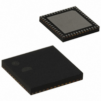
EM250-RTR Ember, EM250-RTR Datasheet - Page 51

EM250-RTR
Manufacturer Part Number
EM250-RTR
Description
IC ZIGBEE SYSTEM-ON-CHIP 48-QFN
Manufacturer
Ember
Series
EM250r
Datasheet
1.EM250-JMP-R.pdf
(117 pages)
Specifications of EM250-RTR
Frequency
2.4GHz
Modulation Or Protocol
802.15.4 Zigbee
Applications
Home/Building Automation, Industrial Control and Monitoring
Power - Output
3dBm
Sensitivity
-97dBm
Voltage - Supply
2 V ~ 3.6 V
Current - Receiving
35.5mA
Current - Transmitting
33mA
Data Interface
PCB, Surface Mount
Memory Size
128kB Flash, 5kB SRAM
Antenna Connector
PCB, Surface Mount
Operating Temperature
-40°C ~ 85°C
Package / Case
48-QFN
For Use With
636-1009 - PROGRAMMER USB FLASH EM250/260
Lead Free Status / RoHS Status
Lead free / RoHS Compliant
Data Rate - Maximum
-
Other names
636-1000-2
Available stocks
Company
Part Number
Manufacturer
Quantity
Price
Company:
Part Number:
EM250-RTR
Manufacturer:
TI
Quantity:
3 400
Part Number:
EM250-RTR
Manufacturer:
EMBER
Quantity:
20 000
SC1_RATEEXP [0x44B2]
SC1_SPICFG [0x44AC]
SC1_RATEEXP
SC_SPIRXDRV
SC_SPIMST
SC_SPIRPT
SC_SPIORD
SC_SPIPHA
SC_SPIPOL
0-R
0-R
0-R
0-R
15
15
0
0
7
0
0
7
0-R
0-R
0-R
0-R
14
14
0
0
6
0
0
6
[3:0]
[5]
[4]
[3]
[2]
[1]
[0]
SC_SPIRXDRV
The exponential component (EXP) of the clock rate as seen in the equation: rate = 24MHz / ( 2 *
(LIN + 1) * (2^EXP) )
Receiver-driven mode selection bit (SPI master mode only). Clearing this bit will initiate trans-
actions when transmit data is available. Setting this bit will initiate transactions when the
receive buffer (FIFO or DMA) has space.
This bit must always be set to put the SPI in master mode (slave mode is not valid).
This bit controls behavior on a transmit buffer underrun condition in slave mode. Clearing this
bit will send the BUSY token (0xFF) and setting this bit will repeat the last byte. Changing this
bit will only take effect when the transmit FIFO is empty and the transmit serializer is idle.
Clearing this bit will result in the Most Significant Bit being transmitted first while setting this
bit will result in the Least Significant Bit being transmitted first.
Clock phase configuration is selected with clearing this bit for sampling on the leading (first
edge) and setting this bit for sampling on second edge.
Clock polarity configuration is selected with clearing this bit for a rising leading edge and
setting this bit for a falling leading edge.
0-RW
0-R
0-R
13
0-R
0
0
5
13
0
5
SC_SPIMST
0-RW
0-R
0-R
12
0-R
0
0
4
12
0
4
SC_SPIRPT
0-RW
0-R
0-RW
11
0
3
0-R
11
0
3
SC_SPIORD
0-RW
0-R
0-RW
10
0
2
0-R
10
0
2
SC1_RATEEXP
SC_SPIPHA
0-RW
0-R
0-RW
0
9
1
0-R
0
9
1
120-0082-000I
EM250
SC_SPIPOL
0-RW
0-RW
0-R
0-R
8
0
0
8
0
0
51


