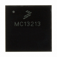
MC13213 Freescale Semiconductor, MC13213 Datasheet - Page 19

MC13213
Manufacturer Part Number
MC13213
Description
IC TXRX RF 2.4GHZ FLSH 60K 71LGA
Manufacturer
Freescale Semiconductor
Series
MC1321xr
Datasheet
1.1321XCSK-BDM.pdf
(70 pages)
Specifications of MC13213
Frequency
2.4GHz
Data Rate - Maximum
250kbps
Modulation Or Protocol
802.15.4 Zigbee
Applications
General Purpose
Power - Output
3dBm
Sensitivity
-92dBm
Voltage - Supply
1.8 V ~ 3.6 V
Current - Receiving
42mA
Current - Transmitting
35mA
Data Interface
PCB, Surface Mount
Memory Size
60kB Flash, 4kB RAM
Antenna Connector
PCB, Surface Mount
Operating Temperature
-40°C ~ 85°C
Package / Case
71-LGA
Number Of Receivers
1
Number Of Transmitters
1
Wireless Frequency
2.4 GHz to 2.48 GHz
Interface Type
SPI
Output Power
0 dBm to 2 dBm
Operating Supply Voltage
2 V to 3.4 V
Maximum Operating Temperature
+ 85 C
Mounting Style
SMD/SMT
Maximum Supply Current
42 mA
Minimum Operating Temperature
- 40 C
Protocol Supported
802.15.4
Lead Free Status / RoHS Status
Lead free / RoHS Compliant
Available stocks
Company
Part Number
Manufacturer
Quantity
Price
Company:
Part Number:
MC13213
Manufacturer:
FREESCALE Semiconductor
Quantity:
337
Part Number:
MC13213
Manufacturer:
FREESCALE
Quantity:
20 000
Company:
Part Number:
MC13213R2
Manufacturer:
BROADCOM
Quantity:
1
Part Number:
MC13213R2
Manufacturer:
FREESCALE
Quantity:
20 000
4.5
For the transmit path, the TX data that was previously written to the internal RAM is retrieved (packet
mode) or the TX data is clocked in via the SPI (stream mode), formed into packets per the 802.15.4 PHY,
spread, and then up-converted to the transmit frequency.
If the 802.15.4 modem is in packet mode, data is processed as an entire packet. The data is first loaded into
the TX buffer. The MCU then requests that the modem transmit the data. The MCU is notified via an
interrupt when the whole packet has successfully been transmitted.
In streaming mode, the data is fed to the 802.15.4 modem on a word-by-word basis with an interrupt
serving as a notification that the 802.15.4 modem is ready for more data. This continues until the whole
packet is transmitted.
In both modes, a two-byte FCS is calculated in hardware from the payload data and appended to the packet.
This done without intervention from the user.
4.6
The following sections provide a detailed description of the MC1321x functionality including the
operating modes and the Serial Peripheral Interface (SPI).
4.6.1
The 802.15.4 modem has a number of operational modes that allow for low-current operation. Transition
from the Off to Idle mode occurs when M_RST is negated. Once in Idle, the SPI is active and is used to
control the IC. Transition to Hibernate and Doze modes is enabled via the SPI. These modes are
summarized, along with the transition times, in
Table
Freescale Semiconductor
Hibernate
Transmit
Receive
Mode
Doze
Idle
Off
8, DC Electrical Characteristics.
Transmit Path Description
Functional Description
802.15.4 Modem Operational Modes
All IC functions Off, Leakage only. M_RST asserted. Digital outputs are tri-stated
including IRQ
Crystal Reference Oscillator Off. (SPI not functional.) IC Responds to ATTN. Data
is retained.
Crystal Reference Oscillator On but CLKO output available only if Register 7, Bit 9
= 1 for frequencies of 1 MHz or less. (SPI not functional.) Responds to ATTN and
can be programmed to enter Idle Mode through an internal timer comparator.
Crystal Reference Oscillator On with CLKO output available. SPI active.
Crystal Reference Oscillator On. Receiver On.
Crystal Reference Oscillator On. Transmitter On.
Table 5. 802.15.4 Modem Mode Definitions and Transition Times
MC13211/212/213 Technical Data, Rev. 1.8
Definition
Table
5. Current drain in the various modes is listed in
10 - 25 ms to Idle
7 - 20 ms to Idle
(300 + 1/CLKO) µs to Idle
144 µs from Idle
144 µs from Idle
Transition Time
To or From Idle
19


