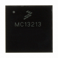
MC13213 Freescale Semiconductor, MC13213 Datasheet - Page 30

MC13213
Manufacturer Part Number
MC13213
Description
IC TXRX RF 2.4GHZ FLSH 60K 71LGA
Manufacturer
Freescale Semiconductor
Series
MC1321xr
Datasheet
1.1321XCSK-BDM.pdf
(70 pages)
Specifications of MC13213
Frequency
2.4GHz
Data Rate - Maximum
250kbps
Modulation Or Protocol
802.15.4 Zigbee
Applications
General Purpose
Power - Output
3dBm
Sensitivity
-92dBm
Voltage - Supply
1.8 V ~ 3.6 V
Current - Receiving
42mA
Current - Transmitting
35mA
Data Interface
PCB, Surface Mount
Memory Size
60kB Flash, 4kB RAM
Antenna Connector
PCB, Surface Mount
Operating Temperature
-40°C ~ 85°C
Package / Case
71-LGA
Number Of Receivers
1
Number Of Transmitters
1
Wireless Frequency
2.4 GHz to 2.48 GHz
Interface Type
SPI
Output Power
0 dBm to 2 dBm
Operating Supply Voltage
2 V to 3.4 V
Maximum Operating Temperature
+ 85 C
Mounting Style
SMD/SMT
Maximum Supply Current
42 mA
Minimum Operating Temperature
- 40 C
Protocol Supported
802.15.4
Lead Free Status / RoHS Status
Lead free / RoHS Compliant
Available stocks
Company
Part Number
Manufacturer
Quantity
Price
Company:
Part Number:
MC13213
Manufacturer:
FREESCALE Semiconductor
Quantity:
337
Part Number:
MC13213
Manufacturer:
FREESCALE
Quantity:
20 000
Company:
Part Number:
MC13213R2
Manufacturer:
BROADCOM
Quantity:
1
Part Number:
MC13213R2
Manufacturer:
FREESCALE
Quantity:
20 000
5.4.2
This section provides a high-level description only.
30
•
•
•
•
•
•
•
•
•
•
•
•
•
•
— Uses external or internal clock as reference frequency
Automatic lockout of non-running clock sources
Reset or interrupt on loss of clock or loss of FLL lock
Digitally-controlled oscillator (DCO) preserves previous frequency settings, allowing fast
frequency lock when recovering from stop3 mode
DCO will maintain operating frequency during a loss or removal of reference clock. When FLL is
engaged (FEE or FEI) loss of lock or loss of clock adds a divide-by-2 to ICG to prevent
over-clocking of the system.
Post-FLL divider selects 1 of 8 bus rate divisors (/1 through /128)
Separate self-clocked source for real-time interrupt
Trimmable internal clock source supports SCI communications without additional external
components
Automatic FLL engagement after lock is acquired
Selectable low-power/high-gain oscillator modes
Mode 1 — Off
The output clock, ICGOUT, is static. This mode may be entered when the STOP instruction is
executed.
Mode 2 — Self-clocked (SCM)
Default mode of operation that is entered out of reset. The ICG’s FLL is open loop and the digitally
controlled oscillator (DCO) is free running at a frequency set by the filter bits.
Mode 3 — FLL engaged internal (FEI)
In this mode, the ICG’s FLL is used to create frequencies that are programmable multiples of the
internal reference clock.
— FLL engaged internal unlocked is a transition state which occurs while the FLL is attempting
— FLL engaged internal locked is a state which occurs when the FLL detects that the DCO is
Mode 4 — FLL bypassed external (FBE)
In this mode, the ICG is configured to bypass the FLL and use an external clock as the clock source.
Mode 5 — FLL engaged external (FEE)
The ICG’s FLL is used to generate frequencies that are programmable multiples of the external
clock reference.
— FLL engaged external unlocked is a transition state which occurs while the FLL is attempting
to lock. The FLL DCO frequency is off target and the FLL is adjusting the DCO to match the
target frequency.
locked to a multiple of the internal reference.
to lock. The FLL DCO frequency is off target and the FLL is adjusting the DCO to match the
target frequency.
Modes of Operation
MC13211/212/213 Technical Data, Rev. 1.8
Freescale Semiconductor


