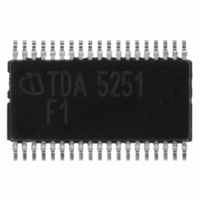
TDA5251 Infineon Technologies, TDA5251 Datasheet - Page 18

TDA5251
Manufacturer Part Number
TDA5251
Description
TXRX FSK/ASK SGL LP TSSOP-38
Manufacturer
Infineon Technologies
Type
Transceiverr
Specifications of TDA5251
Package / Case
38-TSSOP
Frequency
315MHz
Data Rate - Maximum
64kbps
Modulation Or Protocol
ASK, FSK
Applications
RKE, Remote Control Systems
Power - Output
13dBm
Sensitivity
-109dBm
Voltage - Supply
2.1 V ~ 5.5 V
Current - Receiving
9.3mA
Current - Transmitting
14mA
Data Interface
PCB, Surface Mount
Antenna Connector
PCB, Surface Mount
Operating Temperature
-40°C ~ 85°C
Operating Frequency
0.35 MHz
Operating Supply Voltage
2.5 V, 3.3 V, 5 V
Maximum Operating Temperature
+ 85 C
Minimum Operating Temperature
- 40 C
Mounting Style
SMD/SMT
Operating Temperature (min)
-40C
Operating Temperature (max)
85C
Operating Temperature Classification
Industrial
Product Depth (mm)
4.4mm
Product Length (mm)
9.7mm
Operating Supply Voltage (min)
2.1V
Operating Supply Voltage (max)
5.5V
Lead Free Status / RoHS Status
Lead free / RoHS Compliant
Memory Size
-
Lead Free Status / Rohs Status
Compliant
Other names
SP000014554
TDA5251
TDA5251INTR
TDA5251XT
TDA5251
TDA5251INTR
TDA5251XT
Available stocks
Company
Part Number
Manufacturer
Quantity
Price
Company:
Part Number:
TDA5251
Manufacturer:
INFINEON
Quantity:
276
2.4
2.4.1
The power amplifier is operating in C-mode. It can be used in either high or low power mode. In
high-power mode the transmit power is approximately +13dBm into 50 Ohm at 5V and +6dBm at
2.1V supply voltage. In low power mode the transmit power is approximately +12dBm at 5V and -
34dBm at 2.1V supply voltage using the same matching network. The transmit power is controlled
by the D0-bit of the CONFIG register (subaddress 00H) as shown in the following Table 2-2. The
default output power mode is high power mode.
Table 2-2
In case of ASK modulation the power amplifier is turned fully on and off by the transmit baseband
data, i.e. 100% On-Off-Keying.
2.4.2
The LNA is an on-chip cascode amplifier with a voltage gain of 15 to 20dB and symmetrical inputs.
It is possible to reduce the gain to 0 dB via logic.
Table 2-3
2.4.3
The Double Balanced 1
the intermediate frequency (IF) at approximately 105MHz. The local oscillator frequency is
generated by the PLL synthesizer that is fully implemented on-chip as described in Section 2.4.5.
This local oscillator operates at approximately 420MHz in receive mode providing the above
mentioned IF frequency of 105MHz. The mixer is followed by a low pass filter with a corner
frequency of approximately 175MHz in order to prevent RF and LO signals from appearing in the
105MHz IF signal.
2.4.4
The Low pass filter is followed by 2 mixers (inphase I and quadrature Q) that convert the 105MHz
IF signal down to zero-IF. These two mixers are driven by a signal that is generated by dividing the
local oscillator signal by 4, thus equalling the IF frequency.
Data Sheet
Bit
D0
Bit
D4
Functional Block Description
Power Amplifier (PA)
Low Noise Amplifier (LNA)
Downconverter 1
Downconverter 2
LNA_GAIN
Sub Address 00H: CONFIG
Sub Address 00H: CONFIG
Function
PA_PWR
Function
st
Mixer converts the input frequency (RF) in the range of 315MHz down to
st
nd
0= low TX Power, 1= high TX Power
Mixer
I/Q Mixers
0= low Gain, 1= high Gain
18
Description
Description
Functional Description
Default
Default
TDA5251 F1
Version 1.1
1
1
2007-02-26


