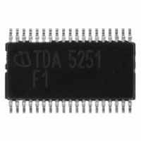
TDA5251 Infineon Technologies, TDA5251 Datasheet - Page 44

TDA5251
Manufacturer Part Number
TDA5251
Description
TXRX FSK/ASK SGL LP TSSOP-38
Manufacturer
Infineon Technologies
Type
Transceiverr
Specifications of TDA5251
Package / Case
38-TSSOP
Frequency
315MHz
Data Rate - Maximum
64kbps
Modulation Or Protocol
ASK, FSK
Applications
RKE, Remote Control Systems
Power - Output
13dBm
Sensitivity
-109dBm
Voltage - Supply
2.1 V ~ 5.5 V
Current - Receiving
9.3mA
Current - Transmitting
14mA
Data Interface
PCB, Surface Mount
Antenna Connector
PCB, Surface Mount
Operating Temperature
-40°C ~ 85°C
Operating Frequency
0.35 MHz
Operating Supply Voltage
2.5 V, 3.3 V, 5 V
Maximum Operating Temperature
+ 85 C
Minimum Operating Temperature
- 40 C
Mounting Style
SMD/SMT
Operating Temperature (min)
-40C
Operating Temperature (max)
85C
Operating Temperature Classification
Industrial
Product Depth (mm)
4.4mm
Product Length (mm)
9.7mm
Operating Supply Voltage (min)
2.1V
Operating Supply Voltage (max)
5.5V
Lead Free Status / RoHS Status
Lead free / RoHS Compliant
Memory Size
-
Lead Free Status / Rohs Status
Compliant
Other names
SP000014554
TDA5251
TDA5251INTR
TDA5251XT
TDA5251
TDA5251INTR
TDA5251XT
Available stocks
Company
Part Number
Manufacturer
Quantity
Price
Company:
Part Number:
TDA5251
Manufacturer:
INFINEON
Quantity:
276
As Figure 3-8 shows, detuning beyond the bandwidth of the matching circuit results in a significant
increase of collector current of the power amplifier and in some loss of output power. This diagram
shows the data for the circuit of the test board at the frequency of 315MHz. The effective load
resistor of this circuit is R L = 250Ohm, which is the optimum impedance for operation at 3V. This will
lead to a dip of the collector current of approx. 20%.
Figure 3-8
C4, L2 and C3||C2 are the main matching components which are used to transform the 50 Ohm
load at the SMA-RF-connector to a higher impedance at the PA-output (250Ohm@3V). L1 can be
used for finetuning of the resonance frequency but should not be too low in order to keep its loss
low.
The transformed impedance of 250Ohm+j0 at the PA-output-pin can be verified with a network
analyzer using this measurement procedure:
1. Calibrate your network analyzer.
2. Connect a short, low-loss 50 Ohm cable to your network analyzer with an open end on one side.
3. Use the „Port Extension“ feature of your network analyzer to shift the reference plane of your
4. Connect the center-conductor of the cable to the solder pad of the pin „PA“ of the IC. The shield
5. Screw a 50Ohm-dummy-load on the RF-I/O-SMA-connector
6. The TDA5251 has to be in ASK-TX-Mode, Data-Input=LOW.
7. Be sure that your network analyzer is AC-coupled and turn on the power supply of the IC.
8. Measure the S-parameter
Data Sheet
Semirigid cable works best.
network analyzer to the open end of the cable.
has to be grounded. Very short connections must be used. Do not remove the IC or any part of
the matching-components!
Power output and collector current vs. frequency
44
TDA5251 F1
Version 1.1
pout_vs_frequ_315.wmf
Application
2007-02-26


