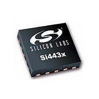
SI4431-B1-FM Silicon Laboratories Inc, SI4431-B1-FM Datasheet - Page 5

SI4431-B1-FM
Manufacturer Part Number
SI4431-B1-FM
Description
IC TXRX 240-930MHZ -8-13DB 20QFN
Manufacturer
Silicon Laboratories Inc
Specifications of SI4431-B1-FM
Package / Case
20-VQFN
Mfg Application Notes
Transitioning SI4430/31 to Rev B
Frequency
240MHz ~ 930MHz
Data Rate - Maximum
256kbps
Modulation Or Protocol
FSK, GFSK, OOK
Applications
General Purpose
Power - Output
13dBm
Sensitivity
-121dBm
Voltage - Supply
1.8 V ~ 3.6 V
Current - Receiving
18.5mA
Current - Transmitting
30mA
Data Interface
PCB, Surface Mount
Antenna Connector
PCB, Surface Mount
Operating Temperature
-40°C ~ 85°C
Wireless Frequency
240 MHz to 930 MHz
Output Power
13 dBm
Operating Supply Voltage
1.8 V to 3.6 V
Maximum Operating Temperature
+ 85 C
Mounting Style
SMD/SMT
Maximum Supply Current
30 mA
Minimum Operating Temperature
- 40 C
Modulation
FSK, GFSK, OOK
Operating Temperature (min)
-40C
Operating Temperature (max)
85C
Operating Temperature Classification
Industrial
Product Depth (mm)
4mm
Product Length (mm)
4mm
Operating Supply Voltage (min)
1.8V
Operating Supply Voltage (typ)
3V
Operating Supply Voltage (max)
3.6V
Lead Free Status / RoHS Status
Lead free / RoHS Compliant
Memory Size
-
Lead Free Status / Rohs Status
Lead free / RoHS Compliant
Available stocks
Company
Part Number
Manufacturer
Quantity
Price
Company:
Part Number:
SI4431-B1-FMR
Manufacturer:
TE
Quantity:
2 000
Part Number:
SI4431-B1-FMR
Manufacturer:
SILICON LABS/èٹ¯ç§‘
Quantity:
20 000
Si4430/31/32-B1
L
F
I S T OF
IGURES
Figure 1. Si4430/31 RX/TX Direct-Tie Application Example ..................................................... 16
Figure 2. Si4432 Antenna Diversity Application Example ......................................................... 16
Figure 3. SPI Timing.................................................................................................................. 18
Figure 4. SPI Timing—READ Mode ..........................................................................................19
Figure 5. SPI Timing—Burst Write Mode .................................................................................. 19
Figure 6. SPI Timing—Burst Read Mode .................................................................................. 19
Figure 7. State Machine Diagram.............................................................................................. 20
Figure 8. TX Timing................................................................................................................... 24
Figure 9. RX Timing .................................................................................................................. 24
Figure 10. Frequency Deviation ................................................................................................ 28
Figure 11. Sensitivity at 1% PER vs. Carrier Frequency Offset ................................................29
Figure 12. FSK vs GFSK Spectrums......................................................................................... 32
Figure 13. Direct Synchronous Mode Example......................................................................... 35
Figure 14. Direct Asynchronous Mode Example ....................................................................... 35
Figure 15. Microcontroller Connections..................................................................................... 36
Figure 16. PLL Synthesizer Block Diagram............................................................................... 38
Figure 17. FIFO Thresholds ...................................................................................................... 41
Figure 18. Packet Structure....................................................................................................... 42
Figure 19. Multiple Packets in TX Packet Handler .................................................................... 43
Figure 20. Required RX Packet Structure with Packet Handler Disabled ................................. 43
Figure 21. Multiple Packets in RX Packet Handler.................................................................... 43
Figure 22. Multiple Packets in RX with CRC or Header Error ................................................... 44
Figure 23. Operation of Data Whitening, Manchester Encoding, and CRC .............................. 46
Figure 24. Manchester Coding Example ...................................................................................46
Figure 25. Header ..................................................................................................................... 48
Figure 26. POR Glitch Parameters............................................................................................ 50
Figure 27. General Purpose ADC Architecture ......................................................................... 52
Figure 28. Temperature Ranges using ADC8 ........................................................................... 54
Figure 29. WUT Interrupt and WUT Operation.......................................................................... 57
Figure 30. Low Duty Cycle Mode .............................................................................................. 58
Figure 31. RSSI Value vs. Input Power..................................................................................... 61
Figure 32. TX/RX Direct-Tie Reference Design—Schematic.................................................... 62
Figure 33. 20-Pin Quad Flat No-Lead (QFN) ............................................................................69
Figure 34. PCB Land Pattern .................................................................................................... 70
Rev 1.1
5


