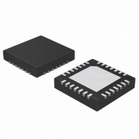
ATA5278-PKQI Atmel, ATA5278-PKQI Datasheet - Page 12

ATA5278-PKQI
Manufacturer Part Number
ATA5278-PKQI
Description
IC ANTENNA DVR STAND-ALONE 28QFN
Manufacturer
Atmel
Type
Stand Alone Antenna Driverr
Datasheet
1.ATA5278-PKQI.pdf
(34 pages)
Specifications of ATA5278-PKQI
Rf Type
TPM
Frequency
125kHz
Package / Case
28-VFQFN
Maximum Operating Temperature
+ 105 C
Mounting Style
SMD/SMT
Minimum Operating Temperature
- 40 C
Lead Free Status / RoHS Status
Lead free / RoHS Compliant
Features
-
Lead Free Status / Rohs Status
Lead free / RoHS Compliant
Other names
ATA5278-PKQITR
3.9
12
LF Data Buffer
ATA5278
The SPI control logic checks the incoming data for valid commands. If the first data word trans-
mitted by the microcontroller does not match any of the above listed functions, an illegal
command fault is detected and written into the fault register. It can be read out with command 9,
bit 5 (IC). Note that this fault does not cause a shut down of the power stages.
The ATA5278 features an 192-bit wide data storage intended to buffer LF data between the
microcontroller and the modulator stage. It can be filled with data via the SPI and therefore at
high speeds (i.e., up to 1 Mbit/s). The modulator stage then accesses this buffer with the
selected LF baud rate and controls the connected LF antenna accordingly. Hence the controller
can handle other tasks during the comparatively slow LF data transmission.
The data buffer is structured as a First-In-First-Out (FIFO) system, as can be seen in
on page
• The status register of the ATA5278 can be read out with command 9. As soon as the internal
• Command 10 accesses a special register, where the actual amount of free logical bits in the
• Command 11 is used to write LF data to the on-chip data buffer and to start the modulator
diagnosis stage detects a fault, it is stored in the status register until a fault reset command is
given or a power-on-reset occurs. Note that the power stages of the chip are disabled as long
as a power stage fault (i.e., a short-circuit at the driver stage output pin, open load,
overcurrent at the current sense pin or over temperature) is present in the status register.
Like all register access commands, it consists of two data words, where the return data in the
second data word contains the fault bits. For further details, please refer to the section
Diagnosis” on page
data buffer is stored. This value decreases with each logical bit that is transferred to the
buffer, and increases with each logical bit the modulator stage fetches from the buffer in order
to transmit it via the LF channel. It can be used to determine the amount of data which can be
transferred to the buffer or to determine the actual modulation process. Like all register
access commands, it consists of two data words, where the second one contains the
six-bit-wide value.
stage. This command is indicated by the most significant bit (MSB) of the first data word from
the controller, which is, in contrast to all other commands, 1. The other seven bits of this word
determine the amount of logical LF data to be written to the buffer. This amount of data has
then to be transferred from the controller to the ATA5278. As one logical bit consists of two
half bits, a maximum of four logical bits can be transferred per one SPI data word. With the
data buffer being able to store up to 96 logical bits, command 11 may reach a maximum
length of 25 SPI data words (i.e., the first word with the amount of data, followed by up to 24
words with the data itself). Note that the input data from the SPI input register is always read
out starting from the least significant bit (LSB), working towards the MSB. So if less than four
logical bits are transferred to the buffer, they have to be stored in the lower area of the SPI
data word (i.e., starting with the LSB). It is important that the number of actually transferred
LF data matches the amount given in the first word of this command, because there are no
consistency checks. This is even then the case if the data buffer was already full at the
beginning of the transmission, or got full during the transmission of LF data, or if the driver
stages are disabled due to a present fault. Data which is transferred under such
circumstances is not stored and therefore lost.
13.
20.
4832D–RKE–12/07
Figure 3-8
“Fault


