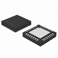
ATA5278-PKQI Atmel, ATA5278-PKQI Datasheet - Page 20

ATA5278-PKQI
Manufacturer Part Number
ATA5278-PKQI
Description
IC ANTENNA DVR STAND-ALONE 28QFN
Manufacturer
Atmel
Type
Stand Alone Antenna Driverr
Datasheet
1.ATA5278-PKQI.pdf
(34 pages)
Specifications of ATA5278-PKQI
Rf Type
TPM
Frequency
125kHz
Package / Case
28-VFQFN
Maximum Operating Temperature
+ 105 C
Mounting Style
SMD/SMT
Minimum Operating Temperature
- 40 C
Lead Free Status / RoHS Status
Lead free / RoHS Compliant
Features
-
Lead Free Status / Rohs Status
Lead free / RoHS Compliant
Other names
ATA5278-PKQITR
3.16
20
Fault Diagnosis
ATA5278
The IC contains several fault diagnosis systems to protect itself from destruction and to provide
diagnosis information. If a fault at the power stages is detected for a certain debounce time, both
the switch mode power supply and the antenna driver stage including the external NMOS tran-
sistor (if present) are switched off and the corresponding fault information is written into the
status register. Also the LF data buffer is cleared. The fault information can be read out with SPI
command 9. In order to restart the operation of the power stages, the status register has to be
cleared by transmitting SPI command 2.
The following protection and diagnosis mechanisms are defined:
Some faults, like open load or a short-circuit of the antenna output pin to ground, can only be
detected while the driver stage is active (i.e., in modulation mode). As the low-side antenna
driver transistor and the QSC transistor are also both active in standby mode, faults concerning
these devices are also monitored then. Only during power-down, no fault monitoring is active.
Figure 3-15 on page 21
• A temperature monitoring system detects critical junction temperatures. Once detected, the
• A short-circuit protection of the antenna driver output is realized by means of internal
• The current through the external high-voltage MOSFET is monitored in order to detect
• The signal at the VSHUNT pin is monitored while the driver stage is active in order to detect
• The input register of the SPI is scanned for illegal commands. Note that this kind of fault will
debounce timer is started. If the temperature is still above the critical limit after the
debouncing time has passed, a fault shutdown is performed.
shunt-voltage monitoring. Both the high-side and the low-side transistors are equipped with a
shunt resistor which provides information about the current flowing through them. If the
current through one of the transistors surpasses the internally defined overcurrent level, a
current limitation is invoked immediately and the debounce timer is started. Should this
condition persist for the whole debouncing time, a fault shutdown is performed.
short-circuits on the return line of the antenna. Like for the other faults, a debounce timer is
started as soon as an overcurrent situation is detected and a fault shutdown is performed
after this time has passed.
a broken antenna connection (i.e., an open load failure). The monitor searches for polarity
changes in the signal and starts the fault debouncing timer if it fails to find such changes. A
fault shutdown is performed if this fault persists for the whole debouncing time.
cause neither a shutdown of the power stages nor a clearing of the LF data buffer. This
diagnosis function is just to provide information about problems on the SPI bus. Also, no
debouncing time is applied for this fault.
illustrates the fault shutdown timing sequence.
4832D–RKE–12/07


