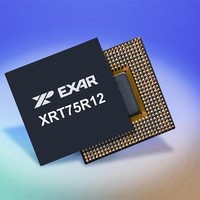
XRT75R12IB-F Exar Corporation, XRT75R12IB-F Datasheet - Page 15

XRT75R12IB-F
Manufacturer Part Number
XRT75R12IB-F
Description
Peripheral Drivers & Components (PCIs) 12 Channel 3.3V-5V temp -45 to 85C
Manufacturer
Exar Corporation
Datasheet
1.XRT75R12IB-F.pdf
(90 pages)
Specifications of XRT75R12IB-F
Maximum Operating Temperature
+ 85 C
Minimum Operating Temperature
- 40 C
Mounting Style
SMD/SMT
Operating Supply Voltage
3.3 V
Package / Case
TBGA-420
Ic Interface Type
Parallel, Serial
Supply Voltage Range
3.135V To 3.465V
Operating Temperature Range
-40°C To +85°C
Digital Ic Case Style
BGA
No. Of Pins
420
Filter Terminals
SMD
Rohs Compliant
Yes
Data Rate Max
51.84Mbps
Lead Free Status / RoHS Status
Lead free / RoHS Compliant
POWER SUPPLY PINS
REV. 1.0.4
P
RVDD10
RVDD11
TVDD10
TVDD11
RVDD0
RVDD1
RVDD2
RVDD3
RVDD4
RVDD5
RVDD6
RVDD7
RVDD8
RVDD9
TVDD0
TVDD1
TVDD2
TVDD3
TVDD4
TVDD5
TVDD6
TVDD7
TVDD8
TVDD9
IN
DVDD
AVDD
N
AME
M25, T25, AB21, AB18,
AF13, AF12, AB9, AB6, R4,
K1, E6, E9, A12, A13, E18,
E21,
D26, F25, H25, P25, W26,
V24, Y22, AF21, AF20, AF17,
AF16, AD14, AD12, AF11,
AF8, AF7, AF24, AD6, AF3,
Y5, V3, W1, P5, P2, H2, F2,
D1, C6, A7, A3, A8, A11, C12,
C14, A16, A17, A20, A21,
A24
TWELVE CHANNEL E3/DS3/STS-1 LINE INTERFACE UNIT WITH JITTER ATTENUATOR
P
IN
AC22
AC18
AB15
AB12
AE23
AE19
AE15
AE10
N
AC5
AE4
D22
D18
E15
E12
AF9
B23
B19
B15
B10
AF6
D5
A9
A6
B4
UMBERS
Receive Analog Power Supply (3.3V ±5%)
RVDD should not be shared with other power supplies. It is recommended
that RVDD be isolated from the digital power supply DVDD and the analog
power supply TVDD. For best results, use an internal power plane for isola-
tion. If an internal power plane is not available, a ferrite bead can be used.
Each power supply pin should be bypassed to ground through an external
0.1 F capacitor.
Transmit Analog Power Supply (3.3V ±5%)
TVDD can be shared with DVDD. However, it is recommended that TVDD be
isolated from the analog power supply RVDD. For best results, use an inter-
nal power plane for isolation. If an internal power plane is not available, a fer-
rite bead can be used. Each power supply pin should be bypassed to ground
through an external 0.1 F capacitor.
Analog Power Supply (3.3V ±5%)
AVDD should be isolated from the digital power supplies. For best results,
use an internal power plane for isolation. If an internal power plane is not
available, a ferrite bead can be used. Each power supply pin should be
bypassed to ground through at least one 0.1 F capacitor.
Digital Power Supply (3.3V ±5%)
DVDD should be isolated from the analog power supplies. For best results,
use an internal power plane for isolation. If an internal power plane is not
available, a ferrite bead can be used. Every two DVDD power supply pins
should be bypassed to ground through at least one 0.1 F capacitor.
12
D
ESCRIPTION
XRT75R12


