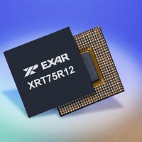
XRT75R12IB-F Exar Corporation, XRT75R12IB-F Datasheet - Page 8

XRT75R12IB-F
Manufacturer Part Number
XRT75R12IB-F
Description
Peripheral Drivers & Components (PCIs) 12 Channel 3.3V-5V temp -45 to 85C
Manufacturer
Exar Corporation
Datasheet
1.XRT75R12IB-F.pdf
(90 pages)
Specifications of XRT75R12IB-F
Maximum Operating Temperature
+ 85 C
Minimum Operating Temperature
- 40 C
Mounting Style
SMD/SMT
Operating Supply Voltage
3.3 V
Package / Case
TBGA-420
Ic Interface Type
Parallel, Serial
Supply Voltage Range
3.135V To 3.465V
Operating Temperature Range
-40°C To +85°C
Digital Ic Case Style
BGA
No. Of Pins
420
Filter Terminals
SMD
Rohs Compliant
Yes
Data Rate Max
51.84Mbps
Lead Free Status / RoHS Status
Lead free / RoHS Compliant
XRT75R12
TWELVE CHANNEL E3/DS3/STS-1 LINE INTERFACE UNIT WITH JITTER ATTENUATOR
SYSTEM-SIDE TRANSMIT INPUT AND TRANSMIT CONTROL PINS
AD23
AC19
AC15
AC23
AC10
AB11
AB19
AB16
P
AD4
AC8
AC4
C23
D19
D15
AB8
D23
D10
E11
E19
E16
M1
M2
M3
M4
M5
C4
D8
D4
N3
N4
N5
N1
E8
L2
K2
J1
IN
#
S
IGNAL
MRing10
MRing11
MRing0
MRing1
MRing2
MRing3
MRing4
MRing5
MRing6
MRing7
MRing8
MRing9
DMO10
DMO11
MTip10
MTip11
DMO0
DMO1
DMO2
DMO3
DMO4
DMO5
DMO6
DMO7
DMO8
DMO9
MTip0
MTip1
MTip2
MTip3
MTip4
MTip5
MTip6
MTip7
MTip8
MTip9
N
AME
T
YPE
O
I
I
Monitor Tip Input - Positive Polarity Signal
These input pins along with MRing_n function as the Transmit Drive Moni-
tor Output (DMO) input monitoring pins. (1) To monitor the Transmit Out-
put line signal and (2) to perform this monitoring externally, then this pin
MUST be connected to the corresponding TTIP_n output pin via a 270
series resistor. Similarly, the MRING_n input pin MUST also be connected
to its corresponding TRING_n output pin via a 270 series resistor.
The MTIP_n and MRING_n input pins will continuously monitor the Trans-
mit Output line signal via the TTIP_n and TRING_n output pins for bipolar
activity. If these pins do not detect any bipolar activity for 128 bit periods,
then the Transmit Drive Monitor circuit will drive the corresponding DMO_n
output pin "High" in order to denote a possible fault condition in the Trans-
mit Output Line signal path.
N
Monitor Ring Input
These input pins along with MTIP_n function as the Transmit Drive Monitor
Output (DMO) input monitoring pins. (1) To monitor the Transmit Output
line signal and (2) to perform this monitoring externally, then this input pin
MUST be connected to the corresponding TRING_n output pin via a 270
series resistor. Similarly, the MTIP_n input pin MUST be connected to its
corresponding TTIP_n output pin via a 270 series resistor.
The MTIP_n and MRING_n input pins will continuously monitor the Trans-
mit Output line signal via the TTIP_n and TRING_n output pins for bipolar
activity. If these pins do not detect any bipolar activity for 128 bit periods,
then the Transmit Drive Monitor circuit will drive the corresponding DMO_n
output pin "High" to indicate a possible fault condition in the Transmit Out-
put Line signal path.
N
Drive Monitor Output
These output signals are used to indicate a fault condition within the Trans-
mit Output signal path.
This output pin will toggle "High" anytime the Transmit Drive Monitor cir-
cuitry either, via the corresponding MTIP and MRING input pins or inter-
nally, detects no bipolar pulses via the Transmit Output line signal (e.g., via
the TTIP_m and TRING_m output pins) for 128 bit-periods.
This output pin will be driven "Low" anytime the Transmit Drive Monitor cir-
cuitry has detected at least one bipolar pulse via the Transmit Output line
signal within the last 128 bit periods.
OTE
OTE
:
:
monitor the Transmit Output line signal.
monitor the Transmit Output line signal.
These input pins are inactive if the user chooses to internally
These input pins are inactive if the user chooses to internally
5
D
ESCRIPTION
REV. 1.0.4


