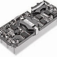
ULE-5/12-D24P-C Murata Power Solutions Inc, ULE-5/12-D24P-C Datasheet - Page 13

ULE-5/12-D24P-C
Manufacturer Part Number
ULE-5/12-D24P-C
Description
DC/DC Converters & Regulators 60W 24V to 5V 12A POSITVE POLARITY
Manufacturer
Murata Power Solutions Inc
Series
ULEr
Type
Step Downr
Specifications of ULE-5/12-D24P-C
Output Power
60 W
Input Voltage Range
18 V to 36 V
Input Voltage (nominal)
24 V
Number Of Outputs
1
Output Voltage (channel 1)
5 V
Output Current (channel 1)
12 A
Isolation Voltage
2.25 KV
Package / Case Size
Eighth Brick
Product
Isolated
Output Current
12A
Input Voltage
24V
Output Voltage
5V
Screening Level
Industrial
Product Length (mm)
58.4mm
Product Depth (mm)
22.9mm
Mounting Style
Through Hole
Pin Count
8
Package / Case
1/8-Brick
Lead Free Status / RoHS Status
Lead free / RoHS Compliant
Other names
ULE-5/12-D24P-C
random deviations or PARD) may be reduced below specifi ed limits using fi lter-
ing techniques, the simplest of which is the installation of additional external
output capacitors. These output caps function as true fi lter elements and
should be selected for bulk capacitance, low ESR and appropriate frequency
response. All external capacitors should have appropriate voltage ratings and
be located as close to the converter as possible. Temperature variations for all
relevant parameters should also be taken carefully into consideration. The most
effective combination of external I/O capacitors will be a function of line volt-
age and source impedance, as well as particular load and layout conditions.
between the power supply and its load. In order to minimize measurement
errors, scope measurements should be made using BNC connectors, or the
probe ground should be less than ½ inch and soldered directly to the fi xture.
Floating Outputs
Since these are isolated DC/DC converters, their outputs are "fl oating" with
respect to their input. Designers will normally use the –Output (pin 4) as the
ground/return of the load circuit. You can, however, use the +Output (pin 8) as
ground/return to effectively reverse the output polarity.
Minimum Output Loading Requirements
ULE converters employ a synchronous-rectifi er design topology and all models
regulate within spec and are stable under no-load to full load conditions.
Operation under no-load conditions however might slightly increase the output
ripple and noise.
Thermal Shutdown
These ULE converters are equipped with thermal-shutdown circuitry. If envi-
ronmental conditions cause the internal temperature of the DC/DC converter to
In critical applications, output ripple/noise (also referred to as periodic and
In Figure 3, the two copper strips simulate real-world pcb impedances
+OUTPUT
–OUTPUT
Figure 3. Measuring Output Ripple/Noise (PARD)
+SENSE
–SENSE
C1 = 0.47µF CERAMIC
C2 = NA
LOAD 2-3 INCHES (51-76mm) FROM MODULE
C1
COPPER STRIP
COPPER STRIP
C2
SCOPE
www.murata-ps.com
R
LOAD
rise above the designed operating temperature, a precision temperature sensor
will power down the unit. When the internal temperature decreases below the
threshold of the temperature sensor, the unit will self start. See Performance/
Functional Specifi cations.
Output Overvoltage Protection
ULE output voltages are monitored for an overvoltage condition via magnetic
feedback. The signal is coupled to the primary side and if the output voltage
rises to a level which could be damaging to the load, the sensing circuitry will
power down the PWM controller causing the output voltages to decrease. Fol-
lowing a time-out period the PWM will restart, causing the output voltages to
ramp to their appropriate values. If the fault condition persists, and the output
voltages again climb to excessive levels, the overvoltage circuitry will initiate
another shutdown cycle. This on/off cycling is referred to as "hiccup" mode.
circuit using a comparator which is optically coupled to the primary side thus
allowing tighter and more precise control.
Current Limiting
As soon as the output current increases to 10% to 50% above its rated value,
the DC/DC converter will go into a current-limiting mode. In this condition, the
output voltage will decrease proportionately with increases in output current,
thereby maintaining somewhat constant power dissipation. This is commonly
referred to as power limiting. Current limit inception is defi ned as the point at
which the full-power output voltage falls below the specifi ed tolerance. See
Performance/Functional Specifi cations. If the load current, being drawn from
the converter, is signifi cant enough, the unit will go into a short circuit condition
as specifi ed under "Performance."
Short Circuit Condition
When a converter is in current-limit mode, the output voltage will drop as
the output current demand increases. If the output voltage drops too low, the
magnetically coupled voltage used to develop primary side voltages will also
drop, thereby shutting down the PWM controller. Following a time-out period,
the PWM will restart causing the output voltages to begin ramping to their
appropriate values. If the short-circuit condition persists, another shutdown
cycle will be initiated. This on/off cycling is referred to as "hiccup" mode. The
hiccup cycling reduces the average output current, thereby preventing internal
temperatures from rising to excessive levels. The ULE is capable of enduring an
indefi nite short circuit output condition.
Features and Options
On/Off Control
The input-side, remote On/Off Control function can be ordered to operate with
either polarity:
suffi x) and these devices are enabled when the On/Off Control is left open or
is pulled high, as per Figure 4. Positive-polarity devices are disabled when the
On/Off Control is pulled low.
Contact Murata Power Solutions for an optional output overvoltage monitor
Standard models are equipped with Positive-polarity (“P" part-number
Isolated, High Density, Eighth-Brick
11 May 2011
1.25–20 Amp, DC/DC Converters
MDC_ULE Series.E01 Page 13 of 26
email: sales@murata-ps.com
ULE Series


