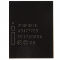
RC28F256P33TFA NUMONYX, RC28F256P33TFA Datasheet - Page 16

RC28F256P33TFA
Manufacturer Part Number
RC28F256P33TFA
Description
IC FLASH 256MBIT 95NS 64EZBGA
Manufacturer
NUMONYX
Series
Axcell™r
Specifications of RC28F256P33TFA
Format - Memory
FLASH
Memory Type
FLASH
Memory Size
256M (16Mx16)
Speed
95ns
Interface
Parallel
Voltage - Supply
2.3 V ~ 3.6 V
Operating Temperature
-40°C ~ 85°C
Package / Case
64-EZBGA
Cell Type
NOR
Density
256Mb
Interface Type
Parallel/Serial
Boot Type
Top
Address Bus
25b
Operating Supply Voltage (typ)
2.5/3/3.3V
Operating Temp Range
-40C to 85C
Package Type
EZBGA
Sync/async
Async/Sync
Operating Temperature Classification
Industrial
Operating Supply Voltage (min)
2.3V
Operating Supply Voltage (max)
3.6V
Word Size
16b
Number Of Words
32M
Supply Current
50mA
Mounting
Surface Mount
Pin Count
64
Lead Free Status / RoHS Status
Contains lead / RoHS non-compliant
Other names
902063
902063
RC28F256P33TF 902063
902063
RC28F256P33TF 902063
Available stocks
Company
Part Number
Manufacturer
Quantity
Price
Company:
Part Number:
RC28F256P33TFA
Manufacturer:
Micron Technology Inc
Quantity:
10 000
Table 11: Value Changes
5.7
Figure 5:
Application Note
16
Num
1
2
3
4
“n” such that typical max. buffer write time-out = 2
“n” such that maximum buffer write time-out = 2
“n” such that maximum number of bytes in write buffer = 2
Page Mode Read capability
bits 0–7 = “n” such that 2n HEX value represents the number of
read-page bytes. See offset 28h for device word width to
determine page-mode data output width. 00h indicates no
read page buffer.
Main Array Representation
Performance Improvements in P33 65nm
The write performance can be increased on P33 65nm by using the 1024 Byte/512
Word buffer. If buffered programming is being done using the 16 word buffer (similar to
130nm devices), no software changes need to be implemented.
To achieve maximum performance using the 1024 Byte/ 512 Word buffer on 65nm
devices, the following considerations apply during software modifications:
1. Use the Full 1024 Byte/ 512 Word Buffer
2. If 1024 Byte/ 512 Word Buffer is being used, the programming addresses should be
aligned in 512 word address boundaries. For example: Start Programming address is
000000h and End Programming Address is 0001FFh. Please refer to Figure 3.
3. If the addresses must be mis-aligned, they must be in chunks of 256 Words. For
example: Start Programming Address to Start Programming Address + 0000FFh (256
Words). Please refer to Figure 3.
The Read performance can be improved by providing read page buffer up to 16 Words
(P+1Dh).
Difference
FFFFFFh
0001FFh
0003FFh
000000h
000200h
Main Array Representation
n
times typical
n
Words
Words
µ-sec
512
512
n
Words
256
(P+1D)h
Words
offset
256
Words
Words
2Ah
20h
24h
256
256
Conversion Guide: P33 130nm to 65nm
130nm
value
1024
512
64
8
Order Number: 320005-04
(P+1D)h
offset
20h
24h
2Ah
65nm
Values
Sep 2008
1024
4096
1024
32


