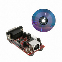
XR21B1411IL-0A-EB Exar Corporation, XR21B1411IL-0A-EB Datasheet

XR21B1411IL-0A-EB
Specifications of XR21B1411IL-0A-EB
Related parts for XR21B1411IL-0A-EB
XR21B1411IL-0A-EB Summary of contents
Page 1
REV. 1.0.0 XR21B1411 USER’S MANUAL WEB CONFIGURATION TOOL USER’S MANUAL 1 ...
Page 2
XR21B1411 USER’S MANUAL WEB CONFIGURATION TOOL USER’S MANUAL 1.0 OVERVIEW............................................................................................................................................... 3 2.0 GPIO PIN CONFIGURATIONS ................................................................................................................ 3 2.1 CONFIGURING THE GPIO PINS IN GPIO MODE .............................................................................................. 3 2.1.1 CONFIGURING GPIO INPUTS ....................................................................................................................................... 4 2.1.1.1 E NABLING INTERNAL PULL 2.1.1.2 E ...
Page 3
REV. 1.0.0 1.0 OVERVIEW The XR21B1411 Enhanced 1-Channel Full-Speed USB UART has internal One-Time-Programmable (OTP) memory that can be used to customize the default settings of the XR21B1411. The web configuration tool for the XR21B1411 from Exar I/O Lab is ...
Page 4
XR21B1411 USER’S MANUAL WEB CONFIGURATION TOOL USER’S MANUAL 2.1.1 Configuring GPIO inputs 2.1.1.1 Enabling internal pull-up or pull-down resistors As an input, a GPIO can have either an internal pull-up or pull-down resistor enabled. The pull-up or pull-down resistor for ...
Page 5
REV. 1.0.0 2.1.2 Configuring GPIO outputs By clicking on the arrows highlighted with the red circle above, the GPIOs will change from inputs to outputs as shown in the image below. Once the GPIO is an output, the block next ...
Page 6
XR21B1411 USER’S MANUAL WEB CONFIGURATION TOOL USER’S MANUAL 2.2 Configuring the GPIO Pins in Auto RTS/CTS Flow Control Mode In Auto RTS/CTS flow control mode, GPIO5/RTS# becomes an output pin and GPIO4/CTS# becomes an input pin. GPIO5/RTS# can not be ...
Page 7
REV. 1.0.0 2.3 Configuring the GPIO Pins in Auto DTR/DSR Flow Control Mode Auto DTR/DSR Flow Control Mode is similar to Auto RTS/CTS Flow Control Mode. In this mode, GPIO3/DTR# is configured as an output and GPIO2/DSR# is configured as ...
Page 8
XR21B1411 USER’S MANUAL WEB CONFIGURATION TOOL USER’S MANUAL 2.4 Configuring the GPIO Pins in Auto Half-Duplex Transceiver Enable Mode The Auto Half-Duplex Transceiver enable mode is typically used in half-duplex RS-485 applications. In this mode the GPIO5/RTS# pin is used ...
Page 9
REV. 1.0.0 3.0 USB CONFIGURATIONS By clicking on the "USB" block, an additional configuration window will appear on the right hand side of the screen, as shown below. 3.1 Entering a Valid Vendor ID and Product ID In this new ...
Page 10
XR21B1411 USER’S MANUAL WEB CONFIGURATION TOOL USER’S MANUAL 3.2 USB Manufacturer, Product, Serial Number Strings The default Manufacturer String is "Exar" and Product String is "XR21B1411" string values have been entered. There is no default value for the ...
Page 11
REV. 1.0.0 4.0 UART SETTING CONFIGURATIONS Clicking on the "UART" block will remove the USB Configuration window and display the "UART Configuration Window" as shown below. XR21B1411 USER’S MANUAL WEB CONFIGURATION TOOL USER’S MANUAL 11 ...
Page 12
XR21B1411 USER’S MANUAL WEB CONFIGURATION TOOL USER’S MANUAL 4.1 Selecting the Core Clock Frequency The available core clock frequencies are 6 MHz, 12 MHz, 24 MHz and 48 MHz. The selection of the core clock frequency will affect the maximum ...
Page 13
REV. 1.0.0 In this example, the VID and PID were not entered. Clicking on "Back to USB" will bring up the "USB Configuration" block where the VID and PIDs can be entered. Once the error has been fixed, click "Check ...
Page 14
... If there are any questions about the web configuration tool, configuration file or the XR21B1411, send your questions to uarttechsupport@exar.com. EXAR Corporation reserves the right to make changes to the products contained in this publication in order to improve design, performance or reliability. EXAR Corporation assumes no responsibility for the use of any circuits described herein, conveys no license under any patent or other right, and makes no representation that the circuits are free of patent infringement ...


