XR21B1411IL-0A-EB Exar Corporation, XR21B1411IL-0A-EB Datasheet - Page 8
XR21B1411IL-0A-EB
Manufacturer Part Number
XR21B1411IL-0A-EB
Description
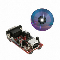
EVAL BOARD UART SR21B1411
Manufacturer
Exar Corporation
Datasheets
1.XR21B1411IL16-F.pdf
(14 pages)
2.XR21B1411IL16-F.pdf
(29 pages)
3.XR21B1411IL-0A-EB.pdf
(2 pages)
Specifications of XR21B1411IL-0A-EB
Mfg Application Notes
Board Design Considerations AppNote
Design Resources
XR21B1411 SP337 Eval Brd Schematic
Interface Type
RS-232, RS-422, RS-485, USB, UART
Operating Supply Voltage
5 V
Product
Interface Modules
Silicon Core Number
XR21B1411
Application Sub Type
UART
Kit Contents
Board
Silicon Manufacturer
Exar
Kit Application Type
Communication & Networking
For Use With/related Products
XR21B1411
Lead Free Status / RoHS Status
Lead free / RoHS Compliant
Lead Free Status / RoHS Status
Lead free / RoHS Compliant, Lead free / RoHS Compliant
Other names
1016-1380


XR21B1411 USER’S MANUAL
WEB CONFIGURATION TOOL USER’S MANUAL
The Auto Half-Duplex Transceiver enable mode is typically used in half-duplex RS-485 applications. In this
mode the GPIO5/RTS# pin is used to control the driver enable of an RS-485 transceiver. When this mode is
selected, the polarity will also need to be selected as active high or active low.
An example of how the Auto Half-Duplex Transceiver enable mode is shown below. The block next to the "TX
EN" also shows whether the selected polarity is active high or active low.
In this mode, GPIO4-GPIO0 can still be configured as described in
in GPIO Mode” on page
2.4
■
■
Active High - The GPIO5/RTS# pin will be low when the UART is not transmitting data and the GPIO5/
RTS# pin will be high when the UART is transmitting data.
Active Low - The GPIO5/RTS# pin will be high when the UART is not transmitting data and the GPIO5/
RTS# pin will be low when the UART is transmitting data.
Configuring the GPIO Pins in Auto Half-Duplex Transceiver Enable Mode
1.
8
“Section 2.1, Configuring the GPIO pins
REV. 1.0.0
Related parts for XR21B1411IL-0A-EB
Image
Part Number
Description
Manufacturer
Datasheet
Request
R

Part Number:
Description:
Enhanced 1-ch Full-speed Usb Uart
Manufacturer:
Exar Corporation
Datasheet:
Part Number:
Description:
BiCMOS Fixed, Quad, Voltage Output, Single or Dual Supply 8-Bit Digital-to-Analog Converter
Manufacturer:
Exar Corporation
Datasheet:
Part Number:
Description:
Manufacturer:
Exar Corporation
Datasheet:
Part Number:
Description:
Voltage-Controlled Oscillator
Manufacturer:
Exar Corporation
Datasheet:
Part Number:
Description:
INTEGRATED LINE TRANSMITTER
Manufacturer:
Exar Corporation
Datasheet:
Part Number:
Description:
Monolithic Function Generator
Manufacturer:
Exar Corporation
Datasheet:
Part Number:
Description:
CMOS Microprocessor Compatible Double-Buffered 12-Bit Digital-to-Analog Converter
Manufacturer:
Exar Corporation
Datasheet:
Part Number:
Description:
CMOS 6 BIT HIGH SPEED ANALOG TO DIGITAL CONVERTER
Manufacturer:
Exar Corporation
Datasheet:
Part Number:
Description:
Manufacturer:
Exar Corporation
Datasheet:
Part Number:
Description:
Manufacturer:
Exar Corporation
Datasheet:
Part Number:
Description:
8-Channel, Voltage Output 10 MHz Input Bandwidth 8-Bit Multiplying DACs with Serial Digital Data Por
Manufacturer:
Exar Corporation
Datasheet:
Part Number:
Description:
15 V CMOS Multiplying10-Bit Digital-to-Analog Converter
Manufacturer:
Exar Corporation
Datasheet:
Part Number:
Description:
Monolithic Function Generator
Manufacturer:
Exar Corporation
Datasheet: