XR21B1411IL-0A-EB Exar Corporation, XR21B1411IL-0A-EB Datasheet - Page 10
XR21B1411IL-0A-EB
Manufacturer Part Number
XR21B1411IL-0A-EB
Description
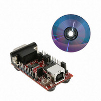
EVAL BOARD UART SR21B1411
Manufacturer
Exar Corporation
Datasheets
1.XR21B1411IL16-F.pdf
(14 pages)
2.XR21B1411IL16-F.pdf
(29 pages)
3.XR21B1411IL-0A-EB.pdf
(2 pages)
Specifications of XR21B1411IL-0A-EB
Mfg Application Notes
Board Design Considerations AppNote
Design Resources
XR21B1411 SP337 Eval Brd Schematic
Interface Type
RS-232, RS-422, RS-485, USB, UART
Operating Supply Voltage
5 V
Product
Interface Modules
Silicon Core Number
XR21B1411
Application Sub Type
UART
Kit Contents
Board
Silicon Manufacturer
Exar
Kit Application Type
Communication & Networking
For Use With/related Products
XR21B1411
Lead Free Status / RoHS Status
Lead free / RoHS Compliant
Lead Free Status / RoHS Status
Lead free / RoHS Compliant, Lead free / RoHS Compliant
Other names
1016-1380


XR21B1411 USER’S MANUAL
WEB CONFIGURATION TOOL USER’S MANUAL
The default Manufacturer String is "Exar" and Product String is "XR21B1411" if no string values have been
entered. There is no default value for the Serial Number String. If one string is entered, then all three strings
need to be updated or they will not have a value when the OTP is programmed. Entering a value for the Serial
Number String is optional.
By default, remote wake-up support is enabled. This can be disabled by unchecking the box. Note that if the
software driver does not have the remote wake-up feature enabled, then the XR21B1411 will not issue a
remote wake-up signal when a remote wake-up event occurs. Note that the standard CDC-ACM driver does
not support the Remote Wake-up feature.
By default, bus-powered mode is enabled. The XR21B1411 can be configured for self-powered mode by
checking the box next to "Self Powered". For self-power mode, it is recommended that the box next to "Enable
VBUS Sense" also be checked. The VBUS Sense feature disables the internal pull-up resistor on the USBD+
pin when there is no power on the VBUS pin. This is required for USB compliance. If the VBUS Sense feature
is not available, then an external mechanism is required to disable the power supply to the XR21B1411.
By default, the USB maximum power is configured as 100 mA. This is the maximum for a low power device, as
described in the USB specifications. Any board that requires more than 100 mA from VBUS will be considered
a high power device. The maximum allowable supply current is 500 mA for a high power device. The USB
max power can be changed by clicking on the arrows on either end of the scroll bar or by dragging the
horizontal scroll bar.
The default polarity of the LOWPOWER pin (pin 1) is active high as shown in the drawing. The polarity can be
changed by clicking on the box below the USB block in the drawing. The inner circle will become yellow to
indicate that the LOWPOWER pin is now active low.
3.2
3.3
3.4
3.5
3.6
USB Manufacturer, Product, Serial Number Strings
Remote Wake-up Support
Selecting the Power Mode
USB Max Power
LOWPOWER Pin Polarity
10
REV. 1.0.0
Related parts for XR21B1411IL-0A-EB
Image
Part Number
Description
Manufacturer
Datasheet
Request
R

Part Number:
Description:
Enhanced 1-ch Full-speed Usb Uart
Manufacturer:
Exar Corporation
Datasheet:
Part Number:
Description:
BiCMOS Fixed, Quad, Voltage Output, Single or Dual Supply 8-Bit Digital-to-Analog Converter
Manufacturer:
Exar Corporation
Datasheet:
Part Number:
Description:
Manufacturer:
Exar Corporation
Datasheet:
Part Number:
Description:
Voltage-Controlled Oscillator
Manufacturer:
Exar Corporation
Datasheet:
Part Number:
Description:
INTEGRATED LINE TRANSMITTER
Manufacturer:
Exar Corporation
Datasheet:
Part Number:
Description:
Monolithic Function Generator
Manufacturer:
Exar Corporation
Datasheet:
Part Number:
Description:
CMOS Microprocessor Compatible Double-Buffered 12-Bit Digital-to-Analog Converter
Manufacturer:
Exar Corporation
Datasheet:
Part Number:
Description:
CMOS 6 BIT HIGH SPEED ANALOG TO DIGITAL CONVERTER
Manufacturer:
Exar Corporation
Datasheet:
Part Number:
Description:
Manufacturer:
Exar Corporation
Datasheet:
Part Number:
Description:
Manufacturer:
Exar Corporation
Datasheet:
Part Number:
Description:
8-Channel, Voltage Output 10 MHz Input Bandwidth 8-Bit Multiplying DACs with Serial Digital Data Por
Manufacturer:
Exar Corporation
Datasheet:
Part Number:
Description:
15 V CMOS Multiplying10-Bit Digital-to-Analog Converter
Manufacturer:
Exar Corporation
Datasheet:
Part Number:
Description:
Monolithic Function Generator
Manufacturer:
Exar Corporation
Datasheet: