EVL90WADP-LLCSR STMicroelectronics, EVL90WADP-LLCSR Datasheet - Page 9
EVL90WADP-LLCSR
Manufacturer Part Number
EVL90WADP-LLCSR
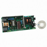
Description
EVAL BOARD PORTABLE PWR SUPPLY
Manufacturer
STMicroelectronics
Type
Power Factor Correctionr
Datasheets
1.L6563HTR.pdf
(49 pages)
2.L6599ADTR.pdf
(36 pages)
3.EVL90WADP-LLCSR.pdf
(29 pages)
4.EVL90WADP-LLCSR.pdf
(28 pages)
Specifications of EVL90WADP-LLCSR
Main Purpose
AC/DC, Primary and Secondary Side with PFC
Outputs And Type
1, Isolated
Power - Output
90W
Voltage - Output
19V
Current - Output
4.75A
Voltage - Input
90 ~ 264VAC
Regulator Topology
Boost
Frequency - Switching
130kHz
Board Type
Fully Populated
Utilized Ic / Part
L6563H, L6599A, SRK2000
Input Voltage
90 V to 264 V
Output Voltage
19 V
Dimensions
65 mm x 155 mm
Product
Power Management Modules
Supply Current
4.75 A
Lead Free Status / RoHS Status
Lead free / RoHS Compliant
For Use With/related Products
L6563H, L6599A, SRK2000
Other names
497-10377


L6563H
Table 3.
10
11 PWM_STOP
12
13
14
15
16
n°
7
8 PWM_LATCH
9
PFC_OK
Name
GND
HVS
RUN
ZCD
N.C.
Vcc
GD
Pin description (continued)
PFC pre-regulator output voltage monitoring/disable function. This pin senses the output
voltage of the PFC pre-regulator through a resistor divider and is used for protection purposes.
If the voltage on the pin exceeds 2.5 V the IC stops switching and restarts as the voltage on the
pin falls below 2.4 V. However, if at the same time the voltage of the INV pin falls below 1.66V, a
feedback failure is assumed. In this case the device is latched off and the PWM_LATCH (8) pin
is asserted high. Normal operation can be resumed only by cycling Vcc bringing its value lower
than 6V before to move up to Turn on threshold.
If the voltage on this pin is brought below 0.23 V the IC is shut down. To restart the IC the
voltage on the pin must go above 0.27 V. This can be used as a remote on/off control input.
Output pin for fault signaling. During normal operation this pin features high impedance. If a
feedback failure is detected (PFC_OK > 2.5 V & INV < 1.66V) the pin is asserted high.
Normally, this pin is used to stop the operation of the dc-dc converter supplied by the PFC pre-
regulator by invoking a latched disable of its PWM controller. If not used, the pin is left floating.
High-voltage start-up. The pin, able to withstand 700 V, is to be tied directly to the rectified
mains voltage. A 1 mA internal current source charges the capacitor connected between pin
Vcc (16) and pin GND (14) until the voltage on the pin Vcc reaches the start-up threshold, then
it is shut down. Normally, the generator is re-enabled when the Vcc voltage falls below 6 V to
ensure a low power throughput during short circuit. Otherwise, when a latched protection is
tripped the generator is re-enabled as Vcc reaches the UVLO threshold to keep the latch
supplied.
Not internally connected. Provision for clearance on the PCB to meet safety requirements.
Output pin for fault signaling. During normal operation this pin features high impedance. If the
IC is disabled by a voltage below 0.8 V on pin RUN (12) the voltage on the pin is pulled to
ground. Normally, this pin is used to temporarily stop the operation of the dc-dc converter
supplied by the PFC pre-regulator by disabling its PWM controller. A typical usage of this
function is brownout protection in systems where the PFC pre-regulator is the master stage. If
not used, the pin is left floating.
Remote ON/OFF control. A voltage below 0.8 V shuts down (not latched) the IC and brings its
consumption to a considerably lower level. PWM_STOP is asserted low. The IC restarts as the
voltage at the pin goes above 0.88V. Connect this pin to pin VFF (5) either directly or through a
resistor divider to use this function as brownout (AC mains undervoltage) protection.
Boost inductor’s demagnetization sensing input for transition-mode operation. A negative-going
edge triggers MOSFET’s turn-on.
Ground. Current return for both the signal part of the IC and the gate driver.
Gate driver output. The totem pole output stage is able to drive power MOSFET’s and IGBT’s
with a peak current of 600 mA source and 800 mA sink. The high-level voltage of this pin is
clamped at about 12 V to avoid excessive gate voltages.
Supply voltage of both the signal part of the IC and the gate driver. Sometimes a small bypass
capacitor (0.1 µF typ.) to GND might be useful to get a clean bias voltage for the signal part of
the IC.
Doc ID 16047 Rev 3
Function
Pin connection
9/49
Related parts for EVL90WADP-LLCSR
Image
Part Number
Description
Manufacturer
Datasheet
Request
R

Part Number:
Description:
STMicroelectronics [RIPPLE-CARRY BINARY COUNTER/DIVIDERS]
Manufacturer:
STMicroelectronics
Datasheet:
Part Number:
Description:
STMicroelectronics [LIQUID-CRYSTAL DISPLAY DRIVERS]
Manufacturer:
STMicroelectronics
Datasheet:

Part Number:
Description:
BOARD EVAL FOR MEMS SENSORS
Manufacturer:
STMicroelectronics
Datasheet:
Part Number:
Description:
NPN TRANSISTOR POWER MODULE
Manufacturer:
STMicroelectronics
Datasheet:
Part Number:
Description:
TURBOSWITCH ULTRA-FAST HIGH VOLTAGE DIODE
Manufacturer:
STMicroelectronics
Datasheet:
Part Number:
Description:
Manufacturer:
STMicroelectronics
Datasheet:
Part Number:
Description:
DIODE / SCR MODULE
Manufacturer:
STMicroelectronics
Datasheet:
Part Number:
Description:
DIODE / SCR MODULE
Manufacturer:
STMicroelectronics
Datasheet:
Part Number:
Description:
Search -----> STE16N100
Manufacturer:
STMicroelectronics
Datasheet:
Part Number:
Description:
Search ---> STE53NA50
Manufacturer:
STMicroelectronics
Datasheet:
Part Number:
Description:
NPN Transistor Power Module
Manufacturer:
STMicroelectronics
Datasheet:
Part Number:
Description:
DIODE / SCR MODULE
Manufacturer:
STMicroelectronics
Datasheet: