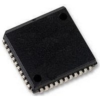
SC28L92A1A NXP Semiconductors, SC28L92A1A Datasheet - Page 21

SC28L92A1A
Manufacturer Part Number
SC28L92A1A
Description
UART, DUAL, 3.3V OR 5V, SMD, 28L92
Manufacturer
NXP Semiconductors
Datasheet
1.SC28L92A1B557.pdf
(73 pages)
Specifications of SC28L92A1A
No. Of Channels
2
Supply Voltage Range
2.97V To 3.63V, 4.5V To 5.5V
Operating Temperature Range
-40°C To +85°C
Digital Ic Case Style
PLCC
No. Of Pins
44
Svhc
No SVHC (18-Jun-2010)
Operating
RoHS Compliant
Data Rate
230.4Kilobaud
Uart Features
Programmable Channel Mode, Line Break Detection & Generation
Rohs Compliant
Yes
Available stocks
Company
Part Number
Manufacturer
Quantity
Price
Company:
Part Number:
SC28L92A1A
Manufacturer:
NXP
Quantity:
677
Company:
Part Number:
SC28L92A1A,512
Manufacturer:
NXP Semiconductors
Quantity:
10 000
Company:
Part Number:
SC28L92A1A,518
Manufacturer:
NXP Semiconductors
Quantity:
10 000
Company:
Part Number:
SC28L92A1A,529
Manufacturer:
NXP Semiconductors
Quantity:
10 000
Company:
Part Number:
SC28L92A1A529
Manufacturer:
NXP Semiconductors
Quantity:
135
NXP Semiconductors
SC28L92_7
Product data sheet
6.3.7 Watchdog
6.3.8 Receiver time-out mode
A receiver reset will discard the present shift register date, reset the receiver ready bit
(RxRDY), clear the status of the byte at the top of the FIFO and realign the FIFO
read/write pointers.
A watchdog timer is associated with each receiver. Its interrupt is enabled by MR0[7]. The
purpose of this timer is to alert the control processor that characters are in the Rx FIFO
which have not been read. This situation may occur at the end of a transmission when the
last few characters received are not sufficient to cause an interrupt.
This counter times out after 64 bit times. It is reset each time a character is transferred
from the receiver shift register to the Rx FIFO or a read of the Rx FIFO is executed.
In addition to the watchdog timer described in
used for a similar function. Its programmability, of course, allows much greater precision of
time-out intervals.
The time-out mode uses the received data stream to control the counter. Each time a
received character is transferred from the shift register to the Rx FIFO, the counter is
restarted. If a new character is not received before the counter reaches zero count, the
counter ready bit is set, and an interrupt can be generated. This mode can be used to
indicate when data has been left in the Rx FIFO for more than the programmed time limit.
Otherwise, if the receiver has been programmed to interrupt the CPU when the receive
FIFO is full, and the message ends before the FIFO is full, the CPU may not know there is
data left in the FIFO. The CTU and CTL value would be programmed for just over one
character time, so that the CPU would be interrupted as soon as it has stopped receiving
continuous data. This mode can also be used to indicate when the serial line has been
marking for longer than the programmed time limit. In this case, the CPU has read all of
the characters from the FIFO, but the last character received has started the count. If
there is no new data during the programmed time interval, the counter ready bit will get
set, and an interrupt can be generated.
The time-out mode is enabled by writing the appropriate command to the command
register. Writing 0xA to CRA or CRB will invoke the time-out mode for that channel.
Writing 0xC to CRA or CRB will disable the time-out mode. The time-out mode should
only be used by one channel at once, since it uses the C/T. If, however, the time-out mode
is enabled from both receivers, the time-out will occur only when both receivers have
stopped receiving data for the time-out period. CTU and CTL must be loaded with a value
greater than the normal receive character period. The time-out mode disables the regular
start counter or stop counter commands and puts the C/T into counter mode under the
control of the received data stream. Each time a received character is transferred from the
shift register to the Rx FIFO, the C/T is stopped after one C/T clock, reloaded with the
value in CTU and CTL and then restarted on the next C/T clock. If the C/T is allowed to
end the count before a new character has been received, the counter ready bit, ISR[3], will
be set. If IMR[3] is set, this will generate an interrupt. Receiving a character after the C/T
has timed out will clear the counter ready bit, ISR[3], and the interrupt. Invoking the set
time-out mode on command, CRx = 0xA, will also clear the counter ready bit and stop the
counter until the next character is received.
Rev. 07 — 19 December 2007
3.3 V/5.0 V Dual Universal Asynchronous Receiver/Transmitter
Section
6.3.7, the counter/timer may be
SC28L92
© NXP B.V. 2007. All rights reserved.
21 of 73


