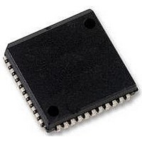
SC28L92A1A NXP Semiconductors, SC28L92A1A Datasheet - Page 31

SC28L92A1A
Manufacturer Part Number
SC28L92A1A
Description
UART, DUAL, 3.3V OR 5V, SMD, 28L92
Manufacturer
NXP Semiconductors
Datasheet
1.SC28L92A1B557.pdf
(73 pages)
Specifications of SC28L92A1A
No. Of Channels
2
Supply Voltage Range
2.97V To 3.63V, 4.5V To 5.5V
Operating Temperature Range
-40°C To +85°C
Digital Ic Case Style
PLCC
No. Of Pins
44
Svhc
No SVHC (18-Jun-2010)
Operating
RoHS Compliant
Data Rate
230.4Kilobaud
Uart Features
Programmable Channel Mode, Line Break Detection & Generation
Rohs Compliant
Yes
Available stocks
Company
Part Number
Manufacturer
Quantity
Price
Company:
Part Number:
SC28L92A1A
Manufacturer:
NXP
Quantity:
677
Company:
Part Number:
SC28L92A1A,512
Manufacturer:
NXP Semiconductors
Quantity:
10 000
Company:
Part Number:
SC28L92A1A,518
Manufacturer:
NXP Semiconductors
Quantity:
10 000
Company:
Part Number:
SC28L92A1A,529
Manufacturer:
NXP Semiconductors
Quantity:
10 000
Company:
Part Number:
SC28L92A1A529
Manufacturer:
NXP Semiconductors
Quantity:
135
NXP Semiconductors
SC28L92_7
Product data sheet
Table 31.
Table 32.
Mode
Normal
Automatic
echo
Local
loopback
Remote
loopback
MR2A[3:0] (hexadecimal)
0
1
2
3
4
5
6
7
8
9
A
DUART mode description
Stop bit length
Description
The transmitter and receiver operating independently.
Places the channel in the automatic echo mode, which automatically retransmits the
received data. The following conditions are true while in automatic echo mode:
Selects local loopback diagnostic mode. In this mode:
Selects remote loopback diagnostic mode. In this mode:
1. Received data is reclocked and retransmitted on the TxDA output
2. The receive clock is used for the transmitter
3. The receiver must be enabled, but the transmitter need not be enabled
4. The channel A TxRDY and TxEMT status bits are inactive
5. The received parity is checked, but is not regenerated for transmission, i.e.
6. Character framing is checked, but the stop bits are retransmitted as received
7. A received break is echoed as received until the next valid start bit is detected
8. CPU to receiver communication continues normally, but the CPU to transmitter
1. The transmitter output is internally connected to the receiver input
2. The transmit clock is used for the receiver
3. The TxDA output is held HIGH
4. The RxDA input is ignored
5. The transmitter must be enabled, but the receiver need not be enabled
6. CPU to transmitter and receiver communications continue normally
1. Received data is reclocked and retransmitted on the TxDA output
2. The receive clock is used for the transmitter
3. Received data is not sent to the local CPU, and the error status conditions are
4. The received parity is not checked and is not regenerated for transmission, i.e.,
5. The receiver must be enabled
6. Character framing is not checked, and the stop bits are retransmitted as received
7. A received break is echoed as received until the next valid start bit is detected
transmitted parity bit is as received
link is disabled
inactive
transmitted parity is as received
Rev. 07 — 19 December 2007
3.3 V/5.0 V Dual Universal Asynchronous Receiver/Transmitter
Stop bit length
0.563
0.625
0.688
0.750
0.813
0.875
0.938
1.000
1.563
1.653
1.688
[1]
SC28L92
© NXP B.V. 2007. All rights reserved.
31 of 73


