DSPIC30F5011-30I/PTG Microchip Technology, DSPIC30F5011-30I/PTG Datasheet - Page 102
DSPIC30F5011-30I/PTG
Manufacturer Part Number
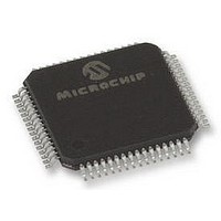
DSPIC30F5011-30I/PTG
Description
16BIT MCU-DSP 30MHZ, SMD, 30F5011
Manufacturer
Microchip Technology
Series
DsPIC30Fr
Datasheet
1.DSPIC30F5011-30IPTG.pdf
(220 pages)
Specifications of DSPIC30F5011-30I/PTG
Core Frequency
30MHz
Embedded Interface Type
CAN, I2C, SPI, UART
No. Of I/o's
52
Flash Memory Size
66KB
Supply Voltage Range
2.5V To 5.5V
Operating Temperature Range
-40°C To
Lead Free Status / RoHS Status
Lead free / RoHS Compliant


dsPIC30F5011/5013
16.3.4
The transmit interrupt flag (U1TXIF or U2TXIF) is
located in the corresponding interrupt flag register.
The transmitter generates an edge to set the UxTXIF
bit. The condition for generating the interrupt depends
on the UTXISEL control bit:
a)
b)
Switching between the two Interrupt modes during
operation is possible and sometimes offers more
flexibility.
16.3.5
Setting the UTXBRK bit (UxSTA<11>) will cause the
UxTX line to be driven to logic ‘0’. The UTXBRK bit
overrides all transmission activity. Therefore, the user
should generally wait for the transmitter to be Idle
before setting UTXBRK.
To send a break character, the UTXBRK bit must be set
by software and must remain set for a minimum of 13
baud clock cycles. The UTXBRK bit is then cleared by
software to generate Stop bits. The user must wait for
a duration of at least one or two baud clock cycles in
order to ensure a valid Stop bit(s) before reloading the
UxTXB, or starting other transmitter activity. Transmis-
sion of a break character does not generate a transmit
interrupt.
16.4
16.4.1
The following steps must be performed while receiving
8-bit or 9-bit data:
1.
2.
3.
4.
5.
DS70116C-page 100
If UTXISEL = 0, an interrupt is generated when
a word is transferred from the transmit buffer to
the Transmit Shift register (UxTSR). This implies
that the transmit buffer has at least one empty
word.
If UTXISEL = 1, an interrupt is generated when
a word is transferred from the transmit buffer to
the Transmit Shift register (UxTSR) and the
transmit buffer is empty.
Set up the UART (see Section 16.3.1).
Enable the UART (see Section 16.3.1).
A receive interrupt will be generated when one
or more data words have been received,
depending on the receive interrupt settings
specified by the URXISEL bits (UxSTA<7:6>).
Read the OERR bit to determine if an overrun
error has occurred. The OERR bit must be reset
in software.
Read the received data from UxRXREG. The act
of reading UxRXREG will move the next word to
the top of the receive FIFO, and the PERR and
FERR values will be updated.
Receiving Data
TRANSMIT INTERRUPT
TRANSMIT BREAK
RECEIVING IN 8-BIT OR 9-BIT
DATA MODE
Preliminary
16.4.2
The receive buffer is 4 words deep. Including the
Receive Shift register (UxRSR), the user effectively
has a 5-word deep FIFO buffer.
URXDA (UxSTA<0>) = 1 indicates that the receive
buffer has data available. URXDA = 0 implies that the
buffer is empty. If a user attempts to read an empty
buffer, the old values in the buffer will be read and no
data shift will occur within the FIFO.
The FIFO is reset during any device Reset. It is not
affected when the device enters or wakes up from a
Power Saving mode.
16.4.3
The receive interrupt flag (U1RXIF or U2RXIF) can be
read from the corresponding interrupt flag register. The
interrupt flag is set by an edge generated by the
receiver. The condition for setting the receive interrupt
flag depends on the settings specified by the
URXISEL<1:0> (UxSTA<7:6>) control bits.
a)
b)
c)
Switching between the Interrupt modes during opera-
tion is possible, though generally not advisable during
normal operation.
16.5
16.5.1
The OERR bit (UxSTA<1>) is set if all of the following
conditions occur:
a)
b)
c)
Once OERR is set, no further data is shifted in UxRSR
(until the OERR bit is cleared in software or a Reset
occurs). The data held in UxRSR and UxRXREG
remains valid.
If URXISEL<1:0> = 00 or 01, an interrupt is gen-
erated every time a data word is transferred
from the Receive Shift register (UxRSR) to the
receive buffer. There may be one or more
characters in the receive buffer.
If URXISEL<1:0> = 10, an interrupt is generated
when a word is transferred from the Receive Shift
register (UxRSR) to the receive buffer, which as a
result of the transfer, contains 3 characters.
If URXISEL<1:0> = 11, an interrupt is set when
a word is transferred from the Receive Shift reg-
ister (UxRSR) to the receive buffer, which as a
result of the transfer, contains 4 characters (i.e.,
becomes full).
The receive buffer is full.
The Receive Shift register is full, but unable to
transfer the character to the receive buffer.
The Stop bit of the character in the UxRSR is
detected, indicating that the UxRSR needs to
transfer the character to the buffer.
Reception Error Handling
RECEIVE BUFFER (U
RECEIVE INTERRUPT
RECEIVE BUFFER OVERRUN
ERROR (OERR BIT)
2004 Microchip Technology Inc.
X
RXB)
Related parts for DSPIC30F5011-30I/PTG
Image
Part Number
Description
Manufacturer
Datasheet
Request
R

Part Number:
Description:
IC DSPIC MCU/DSP 66K 64TQFP
Manufacturer:
Microchip Technology
Datasheet:
Part Number:
Description:
IC,DSP,16-BIT,CMOS,TQFP,64PIN,PLASTIC
Manufacturer:
Microchip Technology
Datasheet:
Part Number:
Description:
IC DSPIC MCU/DSP 66K 64TQFP
Manufacturer:
Microchip Technology
Datasheet:

Part Number:
Description:
High-Performance Digital Signal Controllers
Manufacturer:
MICROCHIP [Microchip Technology]
Datasheet:

Part Number:
Description:
IC, DSC, 16BIT, 66KB, 40MHZ 5.5V TQFP-64
Manufacturer:
Microchip Technology
Datasheet:
Part Number:
Description:
Digital Signal Processors & Controllers - DSP, DSC 16 Bit MCU/DSP 64LD 20M 66KB FL
Manufacturer:
Microchip Technology
Part Number:
Description:
IC DSPIC MCU/DSP 66K 64TQFP
Manufacturer:
Microchip Technology
Datasheet:

Part Number:
Description:
Dspic30f5011/5013 High-performance Digital Signal Controllers
Manufacturer:
Microchip Technology Inc.
Datasheet:
Part Number:
Description:
Manufacturer:
Microchip Technology Inc.
Datasheet:
Part Number:
Description:
Manufacturer:
Microchip Technology Inc.
Datasheet:
Part Number:
Description:
Manufacturer:
Microchip Technology Inc.
Datasheet:
Part Number:
Description:
Manufacturer:
Microchip Technology Inc.
Datasheet: