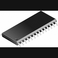
CS8405A-CS Cirrus Logic Inc, CS8405A-CS Datasheet - Page 21

CS8405A-CS
Manufacturer Part Number
CS8405A-CS
Description
Transceiver IC
Manufacturer
Cirrus Logic Inc
Datasheet
1.CS8405A-CS.pdf
(36 pages)
Specifications of CS8405A-CS
Peak Reflow Compatible (260 C)
No
Supply Voltage
5V
Supply Voltage Max
5V
Transceiver Type
Digital Audio
Leaded Process Compatible
No
Mounting Type
Surface Mount
Interface Type
Serial
Package / Case
28-SOIC
Lead Free Status / RoHS Status
Contains lead / RoHS non-compliant
Available stocks
Company
Part Number
Manufacturer
Quantity
Price
Company:
Part Number:
CS8405A-CS
Manufacturer:
SILICOM
Quantity:
89
Part Number:
CS8405A-CS
Manufacturer:
CIRRUS
Quantity:
20 000
Part Number:
CS8405A-CSEP
Manufacturer:
CIRRUS
Quantity:
20 000
Part Number:
CS8405A-CSZ
Manufacturer:
CIRRUS
Quantity:
20 000
8.7
For all bits in this register, a “1” means the associated interrupt condition has occurred at least once since the register
was last read. A ”0” means the associated interrupt condition has NOT occurred since the last reading of the register.
Reading the register resets all bits to 0, unless the interrupt mode is set to level and the interrupt source is still true.
Status bits that are masked off in the associated mask register will always be “0” in this register. This register defaults
to 00h.
8.8
The bits of this register serve as a mask for the Interrupt 1 register. If a mask bit is set to 1, the error is unmasked,
meaning that its occurrence will affect the INT pin and the status register. If a mask bit is set to 0, the error is masked,
meaning that its occurrence will not affect the INT pin or the status register. The bit positions align with the corre-
sponding bits in Interrupt 1 register. This register defaults to 00h.
8.9
The two Interrupt Mode registers form a 2-bit code for each Interrupt Register 1 function. There are three ways to
set the INT pin active in accordance with the interrupt condition. In the Rising edge active mode, the INT pin be-
comes active on the arrival of the interrupt condition. In the Falling edge active mode, the INT pin becomes active
on the removal of the interrupt condition. In Level active mode, the INT interrupt pin becomes active during the in-
terrupt condition. Be aware that the active level(Actice High or Low) only depends on the INT[1:0] bits. These regis-
ters default to 00.
8.10
The bits of this register serve as a mask for the Interrupt 2 register. If a mask bit is set to 1, the error is unmasked,
meaning that its occurrence will affect the INT pin and the status register. If a mask bit is set to 0, the error is masked,
meaning that its occurrence will not affect the INT pin or the status register. The bit positions align with the corre-
sponding bits in Interrupt 2 register. This register defaults to 00h.
DS469PP4
TSLIPM
TSLIP1
TSLIP0
7
0
7
7
7
0
Interrupt 2 Status (8h) (Read Only)
Interrupt 1 Mask (9h)
Interrupt 1 Mode MSB (Ah) and Interrupt 1 Mode LSB(Bh)
Interrupt 2 Mask (Ch)
EFTU - E to F U-buffer transfer interrupt. (Block Mode only)
The source of this bit is true during the E to F buffer transfer in the U bit buffer management process.
00 - Rising edge active
01 - Falling edge active
10 - Level active
11 - Reserved
6
0
6
0
6
0
0
6
0
5
0
5
0
5
0
0
5
0
4
4
4
0
0
4
0
0
0
3
0
3
0
3
0
0
3
0
EFTUM
EFTU
2
2
2
2
0
0
0
EFTCM
EFTC1
EFTC0
1
1
1
1
0
0
CS8405A
0
0
0
0
0
0
0
0
0
21


