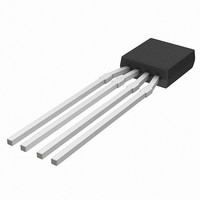
KMZ10C,112 NXP Semiconductors, KMZ10C,112 Datasheet - Page 37

KMZ10C,112
Manufacturer Part Number
KMZ10C,112
Description
IC MAGNETIC FIELD SENSOR SOT195
Manufacturer
NXP Semiconductors
Type
Special Purposer
Specifications of KMZ10C,112
Sensing Range
2mV/V
Voltage - Supply
5 V ~ 10 V
Output Type
Analog
Operating Temperature
-40°C ~ 150°C
Package / Case
SOT-195
Mounting Style
SMD/SMT
Maximum Operating Temperature
+ 150 C
Minimum Operating Temperature
- 40 C
Supply Voltage (min)
5 V
Supply Voltage (max)
10 V
Operating Temperature (min)
-40C
Operating Supply Voltage (typ)
5V
Lead Free Status / RoHS Status
Lead free / RoHS Compliant
Current - Supply
-
Current - Output (max)
-
Features
-
Lead Free Status / Rohs Status
Lead free / RoHS Compliant
Other names
933698480112
KMZ10C T/R
KMZ10C T/R
KMZ10C T/R
KMZ10C T/R
Philips Semiconductors
CURRENT MEASUREMENT
Contents:
Principles
The principle of measuring current with a magnetoresistive
sensor is straightforward. As a current, i, flows through a
wire, it generates a magnetic field around it which is
directly proportional to the current. By measuring the
strength of this magnetic field with a magnetoresistive
sensor, the current can thus be accurately determined.
The relationship between magnetic field strength H,
current i and distance d is given by:
Some calculated values of H for typical conditions are
given in Table 7.
1998 Jun 12
H
handbook, halfpage
Principles
Some practical sensing set-ups
Measurement examples using Philips’ sensors.
Magnetic field sensors
=
Fig.42 Diagram showing field direction in a current
----------
2 d
i
carrying wire.
H
d
MGG423
(14)
37
Table 7 Values for the magnetic field generated by a
Table 7 clearly indicates that current measurement can
involve measurement of weak or strong magnetic fields.
As the sensitivity of magnetoresistive sensors can easily
be adjusted, using different set-ups and different
electronics (refer to the selection guide in the General
section), an individual sensor can be optimized for a
specific current measurement application, a clear
advantage over Hall effect sensors.
The accuracy achievable in current measurement using
magnetoresistive sensors is highly dependent on the
specific application set-up. Factors which affect accuracy
are mechanical tolerances (such as the distance between
the sensor and the wire), temperature drift and the
sensitivity of the conditioning electronics. However, with
Philips magnetoresistive sensors accuracies to within
about 1% are possible.
There is a general difference in the set-up used when
using MR sensors for AC or DC current measurement, due
to the effects of disturbance fields such as the Earth’s
geomagnetic field. For AC currents, disturbing fields can
be eliminating using filtering techniques (similar to those
described in the Chapter “Weak field measurements”),
while for DC currents, compensation techniques must be
used (for example by using two sensors).
Some practical sensing set-ups
D
Philips’ sensors can be used in a number of standard
set-ups for current measurement. The simplest places a
single sensor close to the current carrying wire, to
measure directly the field generated by the current (see
Fig.43). Figure 44 shows how the sensitivity of the sensor
varies with distance from the wire.
EXAMPLE
IRECT MEASUREMENT WITH A SINGLE SENSOR
1
2
3
current carrying wire at various distances and
currents
10 mA
1 A
1000 A
CURRENT
(i)
0.5 mm
0.5 mm
10 mm
DISTANCE
(d)
3.18 A/m
318 A/m
15.9 kA/m
MAGNETIC
General
FIELD (H)


