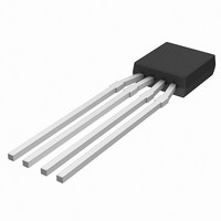
KMZ10C,112 NXP Semiconductors, KMZ10C,112 Datasheet - Page 43

KMZ10C,112
Manufacturer Part Number
KMZ10C,112
Description
IC MAGNETIC FIELD SENSOR SOT195
Manufacturer
NXP Semiconductors
Type
Special Purposer
Specifications of KMZ10C,112
Sensing Range
2mV/V
Voltage - Supply
5 V ~ 10 V
Output Type
Analog
Operating Temperature
-40°C ~ 150°C
Package / Case
SOT-195
Mounting Style
SMD/SMT
Maximum Operating Temperature
+ 150 C
Minimum Operating Temperature
- 40 C
Supply Voltage (min)
5 V
Supply Voltage (max)
10 V
Operating Temperature (min)
-40C
Operating Supply Voltage (typ)
5V
Lead Free Status / RoHS Status
Lead free / RoHS Compliant
Current - Supply
-
Current - Output (max)
-
Features
-
Lead Free Status / Rohs Status
Lead free / RoHS Compliant
Other names
933698480112
KMZ10C T/R
KMZ10C T/R
KMZ10C T/R
KMZ10C T/R
Philips Semiconductors
This circuit shown in Fig.48 is a pre-tested design for
50 Hz currents, delivering very high sensitivity. Two
KM110B/2 sensors are connected in parallel, with
T1 aligned such that the signals produced by external
disturbing fields is minimized. The output signal is then
amplified and DC signal components are considerably
reduced with filtering, through R1-C2 and R2-C3. This
circuit gives the following characteristics:
Amplification: 120 dB (50 Hz)
Sensitivity: 5 V/mA
Noise level: 0.37 V
Max. output: 2.1 V (@ 0.4 mA measured current)
If R1 is adjusted to about 39 k , this changes the data to:
Amplification: 92 dB
Sensitivity: 0.2 V/mA
Noise level: 0.015 V
Max. output: 2.1 V (@ 10 mA measured current)
S
KMZ51
This section describes a practical set-up that can be used
for measuring currents in the metal tracks of a PC-board.
Using the paired sensor approach again, the following
set-up can also be used to measure currents producing
only weak magnetic fields. In this case, the conductor is
also locked mechanically to the sensors, eliminating
variations due to the movement of the conductor and
allowing small currents to be measured to an accuracy of
approximately 1%, with no galvanic connection.
Note: since this involves the measurement of weak
magnetic fields, techniques must be used to suppress the
influence of sensor offset and temperature drift. For more
detailed information on these techniques, refer to the
sections on Flipping and Compensation in Chapter “Weak
field measurements”.
Generally there are several sensor set-ups which can be
used to compensate for the external field. If there are
components on both sides of the PCB, the set-up in Fig.49
can be used.
1998 Jun 12
ENSITIVE MEASUREMENT USING WEAK FIELDS WITH DUAL
Magnetic field sensors
SENSORS
43
The current carrying track is in the centre of the board with
the sensors’ sensitive direction marked with an ‘S’. This
set-up clearly follows the conditions described in
Section “Compensating for external magnetic fields”
earlier (see also Fig.46).
If components are only placed on one side of the PCB,
then the track carrying the current to be measured must be
laid in such a way that the conditions described in
Section “Compensating for external magnetic fields” are
adhered to. Figure 50 illustrates three possible set-ups of
sensor and current-carrier, used in Philips
Semiconductors' demonstration board.
handbook, halfpage
Fig.49 Sensor positioning for current
measurement with double-sided
PC-boards.
S
I
H
H
H
KMZ51
S
d
I
MGG429
General


