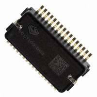
SCC1300-D04 VTI Technologies, SCC1300-D04 Datasheet - Page 2

SCC1300-D04
Manufacturer Part Number
SCC1300-D04
Description
GYRO/ACC COMBO 3-AXIS +/-6G SPI
Manufacturer
VTI Technologies
Datasheet
1.SCC1300-D04_PWB.pdf
(30 pages)
Specifications of SCC1300-D04
Output Type
Digital - SPI
Sensor Type
Gyroscope and Accelerometer
Lead Free Status / RoHS Status
Lead free / RoHS Compliant
Other names
551-1069-2
TABLE OF CONTENTS
1 General Description .........................................................................................4
2 Specifications...................................................................................................6
3 Reset and Power Up ......................................................................................10
4 Component Interfacing ..................................................................................12
VTI Technologies Oy
www.vti.fi
1.1
1.2
1.3
2.1
2.2
2.3
2.4
2.5
3.1
3.2
4.1
4.2
4.3
4.4
4.5
1.2.1
3.2.1
3.2.2
4.2.1
4.2.2
4.3.1
4.3.2
4.4.1
4.4.2
4.4.3
4.5.1
4.5.2
4.5.3
Introduction ..................................................................................................................................4
General Product Description ......................................................................................................4
Abbreviations ...............................................................................................................................5
Performance Specifications for Gyroscope ..............................................................................6
Performance Specifications for Accelerometer........................................................................7
Absolute Maximum Ratings........................................................................................................8
Digital I/O Specification...............................................................................................................8
SPI AC Characteristics ................................................................................................................9
Power-up Sequence for Gyroscope .........................................................................................10
Start-up and Operation Sequence for Accelerometer ............................................................10
SPI Interfaces .............................................................................................................................12
Gyroscope Interface ..................................................................................................................12
Gyroscope ASIC Addressing Space ........................................................................................15
Accelerometer Interface ............................................................................................................16
Accelerometer ASIC Addressing Space ..................................................................................20
Factory Calibration................................................................................................................5
Recommended Start-up Sequence....................................................................................10
Recommended Operation Sequence for Acceleration Data Reading ............................11
SPI Transfer .........................................................................................................................12
SPI Transfer Parity Mode....................................................................................................14
Register Definition ..............................................................................................................15
Data Register Block ............................................................................................................15
Output of Acceleration Data...............................................................................................16
MOSI data of SPI commands..............................................................................................18
Error Conditioning ..............................................................................................................18
Register Map of Accelerometer .........................................................................................20
Control Register (CTRL) .....................................................................................................21
Temperature Output Registers ..........................................................................................21
Doc.Nr. 82 1131 00 A
Subject to changes
SCC1300-D04
Rev. 1.0
2/30


