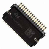
SCC1300-D04 VTI Technologies, SCC1300-D04 Datasheet - Page 23

SCC1300-D04
Manufacturer Part Number
SCC1300-D04
Description
GYRO/ACC COMBO 3-AXIS +/-6G SPI
Manufacturer
VTI Technologies
Datasheet
1.SCC1300-D04_PWB.pdf
(30 pages)
Specifications of SCC1300-D04
Output Type
Digital - SPI
Sensor Type
Gyroscope and Accelerometer
Lead Free Status / RoHS Status
Lead free / RoHS Compliant
Other names
551-1069-2
5.2 Application Circuitry and External Component Characteristics
VTI Technologies Oy
www.vti.fi
pin #
24
25
26
27
28
29
30
31
32
Name
RESERVED
RESERVED
RESERVED
RESERVED
AVDD_G
SCK_G
CSN_G
HEAT
Notes:
1) A=Analog, D=Digital, I=Input, O=Output, Z=Tristate Output, R = Reserved
3) PU=internal pullup, PD=internal pulldown, HV = high voltage
See recommended schematics in Figure 12. Component characteristics are presented in Table 18.
Figure 12. SCC1300 recommended circuit diagram.
Optional filtering recommendations for better PSRR (Power Supply Rejection Ratio) is presented in
Figure 13. Please note that PSSR filtering is optional and not required if the 3.3V power supply is
already stabile enough. RC filtering (R1 & C7 without L2) could also be sufficient for most cases.
SUB
Type 1)
A1
DI
DI
AI
AI
R
R
R
R
PD/PU/HV 3)
Doc.Nr. 82 1131 00 A
Subject to changes
PD
PU
Description
Clk Signal of SPI Interface, 3.3V level Schmitt-trigger input, Input Clock
range 2 to 8MHz. Level definition see SPI-section
Chip Select of SPI Interface, 3.3V level Schmitt-trigger input, Input Clock
range 2 to 8MHz. Level definition see SPI-section
Factory used only, leave floating
Factory used only, leave floating
Analog Supply voltage
Connected external to AVSS_G
Factory used only, leave floating
Factory used only, leave floating
Heat sink connection, externally connected to AVSS_G.
SCC1300-D04
Rev. 1.0
23/30


